Help us help you. By posting the year, make, model and engine near the beginning of your help request, followed by the symptoms (no start, high idle, misfire etc.) Along with any prevalent Diagnostic Trouble Codes, aka DTCs, other forum members will be able to help you get to a solution more quickly and easily!

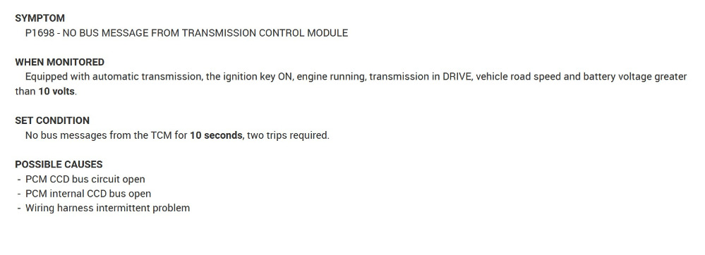
p1698 2000 dodge dakota sport 4x4 with a 318 v8

More
4 years 5 months ago - 4 years 5 months ago #34895 by jetter3606
changed speed sensors , shift solenoid ,transmission computer ...still in limp mode with all gear indicator lights on checked power and grounds to tcm . doesn't seem to be turning on trans relay
Last edit: 4 years 5 months ago by jetter3606.
The following user(s) said Thank You: aboudi.naddaf

Please Log in or Create an account to join the conversation.

More
4 years 5 months ago #34897 by Chad
This is a comunication fault, between the PCM and TCM. Check for wire integrity between the two.


File Attachment:

File Name: 2000DakotaComs.pdf
File Size:247 KB

"Knowledge is a weapon. Arm yourself, well, before going to do battle."
"Understanding a question is half an answer."

I have learned more by being wrong, than I have by being right. :-)
Attachments:
The following user(s) said Thank You: jreardon, aboudi.naddaf

Please Log in or Create an account to join the conversation.

More
4 years 5 months ago - 4 years 5 months ago #34906 by jetter3606
I checked continuity between the pcm and tcm on the white black and violet tan wires and it was good, Started truck and got a voltage reading of 2.5 vdc on each wire .. its suppossed to be 4.7 .. im not sure what the next step is in finding the low voltage issue . the wires go from the tcm into the wiring bundle going down firewall and return at the pcm
Last edit: 4 years 5 months ago by jetter3606.
The following user(s) said Thank You: aboudi.naddaf

Please Log in or Create an account to join the conversation.

More
4 years 5 months ago #34908 by Cheryl
Hope chad can post the flow chart and wiring diagrams. Possibly what ccd wire voltage is supposed to be
The following user(s) said Thank You: aboudi.naddaf

Please Log in or Create an account to join the conversation.

More
4 years 5 months ago #34910 by Cheryl
Never mind I see the diagram.
The following user(s) said Thank You: aboudi.naddaf

Please Log in or Create an account to join the conversation.

More
4 years 5 months ago #34911 by Cheryl
Just out of curiosity what does the ccd wires read at the abs module? Got a scope? Those two wires go to every other module
The following user(s) said Thank You: aboudi.naddaf

Please Log in or Create an account to join the conversation.

More
4 years 5 months ago #34912 by Cheryl
Or just test at the data link connector
The following user(s) said Thank You: aboudi.naddaf

Please Log in or Create an account to join the conversation.

More
4 years 5 months ago #34913 by jreardon
The following user(s) said Thank You: aboudi.naddaf

Please Log in or Create an account to join the conversation.

More
4 years 5 months ago #34914 by jetter3606
yeah Im not sure what pin to check for voltage at the data link conn I think its pin 16 but unsure if its labeled or if thats the right spot to check all abs and other functions are normal with no codes just the p1698
The following user(s) said Thank You: aboudi.naddaf

Please Log in or Create an account to join the conversation.

More
4 years 5 months ago - 4 years 5 months ago #34915 by jetter3606
i did check for continuity looking for a short between the two wires no continuity but had 600 .ohms of resistance between the two
Last edit: 4 years 5 months ago by jetter3606.
The following user(s) said Thank You: aboudi.naddaf

Please Log in or Create an account to join the conversation.

More
4 years 5 months ago #34916 by Cheryl
Pin 3 and 11 at dlc. Previous member posted a good article about ccd information. So transmission relay not turning on??
The following user(s) said Thank You: aboudi.naddaf

Please Log in or Create an account to join the conversation.

More
4 years 5 months ago #34917 by Cheryl
It’s a dodge it needs a pcm lol. I’m going to check alldata for the code flowchart tomorrow
The following user(s) said Thank You: aboudi.naddaf

Please Log in or Create an account to join the conversation.

More
4 years 5 months ago - 4 years 5 months ago #34918 by jetter3606
im working on this truck for my teenage stepson a friend at work brought it to me to try to fix because he gave up on it it but its been a real challenge and i dont give up easy in the mean time ...Ill try not to shoot it full of holes . Im not a big dodge fan so its all new to me thanks for the insight it really helps
Last edit: 4 years 5 months ago by jetter3606.
The following user(s) said Thank You: aboudi.naddaf

Please Log in or Create an account to join the conversation.

More
4 years 5 months ago #34919 by Chad
Flow chart:

File Attachment:

File Name: P1698Flow1.pdf
File Size:142 KB

File Attachment:

File Name: P1698Flow2.pdf
File Size:269 KB

"Knowledge is a weapon. Arm yourself, well, before going to do battle."
"Understanding a question is half an answer."

I have learned more by being wrong, than I have by being right. :-)
Attachments:
The following user(s) said Thank You: aboudi.naddaf

Please Log in or Create an account to join the conversation.

More
4 years 5 months ago - 4 years 5 months ago #34931 by jetter3606
I dont have a DRBIII scanner I did check the ABS connector and had the same 2.5 volts on the pins with the white black and violet tan wires . does this mean I need a new PCM or is there another way to verify the PCM with a volt meter or obII scanner . I noticed a P1687 code that just popped up also but I assume thats from my testing I did . not sure
Last edit: 4 years 5 months ago by jetter3606.
The following user(s) said Thank You: aboudi.naddaf

Please Log in or Create an account to join the conversation.

More
4 years 5 months ago #34934 by Cheryl
Step 4 in the chart is really the determining step to determine if the ccd bus is messed up. You could possibly use a voltmeter on the pci bus wire but you won’t see detail like you would with a scope. Then again you could do it in 2 places again and compare what you get. I’d check powers and grounds at pcm before calling it though
The following user(s) said Thank You: aboudi.naddaf

Please Log in or Create an account to join the conversation.

More
4 years 5 months ago #34936 by VegasJAK
flow chart from jreardon post 3419 says if you have 2.5v on terminal 3 (vio/brn) wire and terminal 11 (wht/blk) wire you have a short between the two wires somewhere. Terminal 3 should be 2.45 and terminal 11 2.47

look for contact points on the wiring loom... where loom comes in contact with metal. do this before you start pulling wires apart or you may loose finding the contact first. keep your DVOM connected and touch the loom at possible contact points and watch the DVOM for any voltage change.

"an open mind let's knowledge flow in and wisdom flow out for a man who has neither never listens to those who have both".
Being wrong doesn't bother me, it's being right and not understanding why that does
The following user(s) said Thank You: aboudi.naddaf

Please Log in or Create an account to join the conversation.

More
4 years 5 months ago #34937 by jetter3606
I checked the Data link connector at pin 3 and 11,both had 2.5 VDC.same as all other spots checked .. not sure if this is a good reading or is it supposed to be the 4.7 vdc reference at the spots checked . there are no other issues with the truck other than the limp mode condition of the transmission .. it starts and runs normal so Im still unsure If I need to pick up the pcm from the junkyard and try it or not
The following user(s) said Thank You: aboudi.naddaf

Please Log in or Create an account to join the conversation.

More
4 years 5 months ago #34938 by Cheryl
What color is key? If it’s grey it needs skim programming. If it’s black it’s no security programming
The following user(s) said Thank You: aboudi.naddaf

Please Log in or Create an account to join the conversation.

More
4 years 5 months ago #34939 by jetter3606
my volt meter only reads to .o one had 2.4 actually and one had 2.5 at the datalink connector same as by the pcm, tcm ,and abs, inputs locations
The following user(s) said Thank You: aboudi.naddaf

Please Log in or Create an account to join the conversation.

Time to create page: 0.310 seconds