2013 Nissan Frontier intermittent p2127 and p2138
- Chaosminionx
-
 Topic Author
- Offline
- New Member
-

- Posts: 10
- Thank you received: 0
I have been trying to track down an extremely temperamental P2127 and P2138 code that I get on my 2013 Nissan Frontier with a 5.6L VK56DE engine swap (engine from a Nissan Titan), custom intake manifold with a Nick Williams 102mm DBW throttlebody (GM TB, 6pin plug), 525CC injectors, Walbro lph255 fuel pump.
Before we fault the engine being swapped, this swap has been done so that everything is 100% native to the vehicle. It used a 2013 Nissan Titan ECM, a repinned harness that accounts for the subtle difference in the Frontier wiring and Titan wiring, and the BCM has been reprogrammed at the dealer for the security features, and the VIN was updated on the ECM. There are no codes disabled, indicator lights, or other issues. For all intents and purposes it's basically a Nissan Titan stuffed into a Nissan Frontier chassis. Even the dealer couldn't pull up anything odd from the CONSULT side of things.
Now to my problem:
Ever so often I get a P2127 and P2138. On the scanner that I do have I can see that APP2 gets zeroed out when the fault triggers. Besides that it just takes turning vehicle off for a bit, or forcing the ECM to reset in order to get driving again. The truck has no operational issues that I can see until this code pops. Sometimes I can go 300+ miles and no issue, sometimes it's just idling in my driveway and goes.
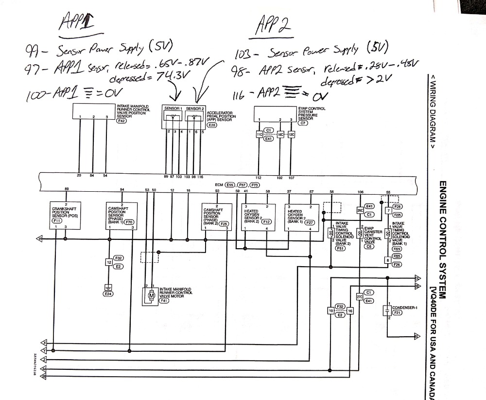
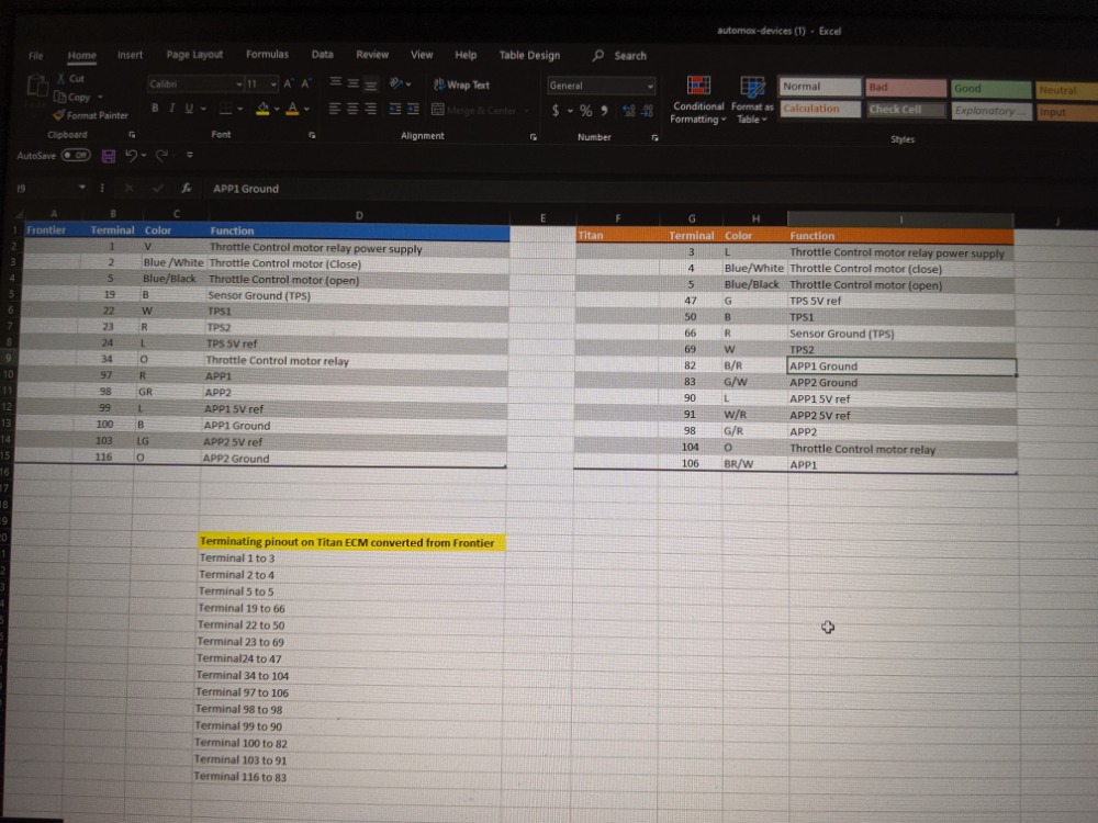
In accordance with the Nissan FSM I have run through all the voltage validations, and operational voltage changes and it all checks out, I have also checked those APP1 and APP2 connections at ECM for proper voltage as well. TPS1 and TPS2 also read correctly, and the pinout change from the 6pin Nissan connector to the 6 pin GM connector for this TB was done correctly and exists on quite a few Nissan Trucks and they never experienced this issue.
I have meticulously gone over the APP1, APP2, TPS1 and TPS2 wiring and it all checks out, I have also validated the 5V ref and voltages running to the pedal assembly and the Throttlebody and those check out as well. The wiring harness was also wiggled/poked/prodded to try and trigger the fault codes again but never could get it to trigger on demand, I have also reviewed all the wiring for being seated into the connector, clean, and free of abrasion/damage (that I can see) and no dice.
I have a new Odyssey Extreme AGM battery, it's been maintained on a ctek 4.3MUS charger and the voltages were all good.
All grounds have been investigated as well, cleaned of corrosion and cleaned in the body/frame to give metal to metal contact. Resistance in the grounds I read at .03V. I have also added 4GA grounding wires to help since the stock Nissan ones leave much to be desired.
I have replaced:
Pedal assembly (contains APP1 and 2)
Throttlebody (contains TPS1 and 2), I have used both a 90mm ACDelco, and 2 102mm Nick Williams throttlebodys
ECM, I used another 2013 Titan ECM and same issue.
I have checked the relays and fuses and all are good.
I started to investigate the EVAP system since it's on the 5V circuit, and if a problem there were to exist it would trigger the APP/TPS potential since from my understanding APP and TPS are a high priority 5V sensor. I replaced the evap canister pressure sensor as I had received codes for that before but I saw no change after replacement.
I have been going crazy trying to get this solved for 3+ months and just can't seem to pin it down so I am hoping someone here could help, maybe something I overlooked.
Today I was letting my truck idle in the driveway, it was out there for about 30minutes. 80F outside, coolant temp was 184F, throttlebody housing was 140F.
As I was going to turn it off the truck very briefly had the idle RPMs dip, or like a dip in the operation sound and then recovered and it posted a p2138/p2127. Does this seem consistent with the procedures it does to put a vehicle into limp mode, or does it seem like the codes are coming as the result of a system like the EVAP circuit purging.
There are quite a few Nissan Frontiers with the 5.6L swap now and nobody has had this issue in the 4+ years it's been offered, and also for the intake manifold and the GM throttlebody it's been used extensively on the Titan platform with no issues of this nature. The frontier and Titan also have almost identical reference ranges for APP and TPS so it does not appear to be caused by this, as I am operating within range if both specs.
Thank you in advance for any ideas/help!
Please Log in or Create an account to join the conversation.
- Cheryl
-
- Offline
- Platinum Member
-

- Posts: 1216
- Thank you received: 215
Please Log in or Create an account to join the conversation.
- Chaosminionx
-
Topic Author
- Offline
- New Member
-
- Posts: 10
- Thank you received: 0
Question: since the ECM is going into "limp mode" once the p2127 and 2138 are triggered is it not doing that by pulling the APP2 voltage? I guess before I thought maybe the APP2 voltage getting zeroed out would have been a function of the ECM going into that safety mode.
If that's not the case then you might be on to something about 5V having issues..
Since it's an intermittent issue how would I go about using a scope or graphing DMM to show the problem, or do I use that after the codes trigger? I have the resources to acquire tools like that so it's not out of the question to get one to help track this down.
Please Log in or Create an account to join the conversation.
- Chaosminionx
-
Topic Author
- Offline
- New Member
-
- Posts: 10
- Thank you received: 0
If you see anything else of interest here let me know and I can lookup what it is.
Please Log in or Create an account to join the conversation.
- Cheryl
-
- Offline
- Platinum Member
-
- Posts: 1216
- Thank you received: 215
Please Log in or Create an account to join the conversation.
- Cheryl
-
- Offline
- Platinum Member
-
- Posts: 1216
- Thank you received: 215
Please Log in or Create an account to join the conversation.
- Chaosminionx
-
Topic Author
- Offline
- New Member
-
- Posts: 10
- Thank you received: 0
Cheryl wrote: Or go across the 5 volt ref and ground at the pedal on both sensors. Such as pin 99 and 100 for app 1 and 103 and 116 at the pedal That’d rule out the power and ground for both sensors if you keep scoping it until the malfunction occurs and neither drop out
Would the picoscope 2204A be sufficient? It looks like it does dual channel as well.
Please Log in or Create an account to join the conversation.
- Cheryl
-
- Offline
- Platinum Member
-
- Posts: 1216
- Thank you received: 215
Please Log in or Create an account to join the conversation.
- Donut
-
- Offline
- Senior Member
-

- Posts: 50
- Thank you received: 11
"Don't ever say 'easy' until the check clears."
Please Log in or Create an account to join the conversation.
- Chaosminionx
-
Topic Author
- Offline
- New Member
-
- Posts: 10
- Thank you received: 0
Donut wrote: I use the 2204A as my daily driver and it's more than enough to handle this. I'd backprobe the 5v and signal or ground and put the scope on the longest time base that covers the time you're driving it. Just have to do that every time you're in it to hopefully catch it in the act. The current Pico software can log up to 13h on a screen, so no worries on the capture time.
Beautiful! That's very handy to know, I was actually wondering what the capture time capabilities were. I saw the 2204A isn't rated for investigating things like ignition and coilpacks, but I figured 5V should be perfectly fine. Thanks for that reply!
Please Log in or Create an account to join the conversation.
- Donut
-
- Offline
- Senior Member
-
- Posts: 50
- Thank you received: 11
"Don't ever say 'easy' until the check clears."
Please Log in or Create an account to join the conversation.
- Chaosminionx
-
Topic Author
- Offline
- New Member
-
- Posts: 10
- Thank you received: 0
This was idling in my driveway, does this show any thing definitively? This is a brand new accelerator pedal assembly, but I'm not sure what would be causing such erratic voltage swings while idling, I am guessing it's the same behavior for driving too.
APP1 stays pretty consistent with only a .01V fluctuation during running.
I have an oscilloscope coming, but had this in the meantime. Thank you for the assistance!
Please Log in or Create an account to join the conversation.
- Donut
-
- Offline
- Senior Member
-
- Posts: 50
- Thank you received: 11
Hardest part about it is you may have to catch that very limited window while it's malfunctioning to see what's happening at those sensors and the ECM. I wonder if there's anything that shares the APP2 reference voltage inside the ECM? Anything random look out of the ordinary on freeze frame data?
As much as I want to blame the IPDM for this, because I've seen them do some crazy stuff when they go bad, it doesn't look to have much of a role in this system except housing the throttle control relay and fuse.
"Don't ever say 'easy' until the check clears."
Please Log in or Create an account to join the conversation.
- Chaosminionx
-
Topic Author
- Offline
- New Member
-
- Posts: 10
- Thank you received: 0
I found that the AC pressure sensor, and EVAP pressure sensor are also on the same 5V circuit, but for this testing I removed their connectors to try and isolate it.
APP1 and APP2 have their own independent grounds and 5V ref as well. It was suggested that it may be heatsoak considering the sensor "behaves" for the first bit of use, and not until engine bay starts getting hot does it start to get erratic, possibly suggesting either a bad ground to the sensor or damaged wiring.
I have 2 different ECMs on hand for a 2013 Titan pro4x 4x4 and both exhibit the same issue, I haven't touched the IPDM yet as it didn't look like from the FSM that it had much to do with the issues I am seeing, but yes I have seen them to bad and act funny. I also have 2 different pedal assemblies I have tried and same behavior (2013 and a 2019 build date assembly).
I have another log going from cold to hot on the vehicle now, going to see if the voltage disturbances do indeed coincide with heat build up. I may also try swapping the APP1 and APP2 grounds at the connector and see if the behavior jumps over to APP1 with the ground move.
Attached is the wiring I've broken down from FSMs
Please Log in or Create an account to join the conversation.
- Donut
-
- Offline
- Senior Member
-
- Posts: 50
- Thank you received: 11
This may be easier with a scope, but do a KOEO throttle sweep while monitoring the output voltages of both the throttle sensors. They should have an inversely proportional sweep, so TP2 should be .5v at WOT and TP1 should be 4.5v roughly.
Why that would pull APP2 reference voltage all out of whack I'm not sure, but it's a start.
"Don't ever say 'easy' until the check clears."
Please Log in or Create an account to join the conversation.
- Chaosminionx
-
Topic Author
- Offline
- New Member
-
- Posts: 10
- Thank you received: 0
However I have some good news, I have isolated where my issue is... Guessing either APP2 sensor wire itself, the 5V ref for APP2 or the ground for APP2 is damaged. Video below is pretty black and white on where my issue is haha.
I guess it could be something weird with pin contact too, so I am going to unbundle that set of wires and work on all the APP2 wires in there and if I can identify where the problem is. Thankfully the run of wires from the 3rd ECM connector only runs for about 12" before they go into the 2nd ECM connector so I don't have a huge run of wire to troubleshoot.
Please Log in or Create an account to join the conversation.
- Donut
-
- Offline
- Senior Member
-
- Posts: 50
- Thank you received: 11
It's good that it isn't just haunted. My next suggestion would have been to call a priest.
"Don't ever say 'easy' until the check clears."
Please Log in or Create an account to join the conversation.
- Chaosminionx
-
Topic Author
- Offline
- New Member
-
- Posts: 10
- Thank you received: 0
So I can only get that section of harness to misbehave once the vehicle has been running for a bit and it gets hot (harness on IR is 140F) and I can't seem to identify any one wire within that bundle that causes the behavior, only once I wiggle the whole bundle back and forth together does it cause the voltage fluctuations.
Since it's only APP2 that is having the issue I guess I'm going to have to cut APP2 off that part of the harness and direct jump it to the 2nd ECM connector. Basically this section of the harness only serves the purpose of connecting parts of the engine room harness to the 2nd plug on the ECM.
Please Log in or Create an account to join the conversation.