1996 Dodge Ram 2500 stalls V10
- cfiigep
-
 Topic Author
- Offline
- New Member
-

- Posts: 8
- Thank you received: 0
I have bypassed the ASD relay to keep it running, and have measured the voltage from connector A of the PCM. According to my Dodge service manual;
1 - GY/BK is the crank sensor
2 - BK/LB is sensor ground
3 - TN/YL is the cam sensor
4 - VT/WT is 5 volts
Using a Fluke single trace 867 graphing voltmeter, I am not seeing exactly what I think I should be seeing.
The 5 volt line reads battery voltage, not 5 volts.
The crank sensor is showing what I expect to see, a 5 volt and ground referenced square wave pulsed signal.
The cam sensor is showing a bi-polar 5 volt triangle wave. 2.5 volts above and below signal ground reference.
I am not sure of the signal ground should read battery ground, as this ground reference is coming from the PCM.
My initial thought is that the new PCM is not completely compatible with the one I removed. However, I am not sure how I am getting the triangle wave from the cam sensor, or why I am seeing battery voltage on what should be a 5 volt line according to the Dodge service manual.
Where does the PCM ground? I know a funky ground can cause problems.
If I wind up needing a crank sensor, Dodge also has stopped supporting this part. Not a lot of luck in the aftermarket, either. If you have a work around or alternate supplier, would be nice to know about.
Thanks in advance for any suggestions or guidance.
Please Log in or Create an account to join the conversation.
- cfiigep
-
Topic Author
- Offline
- New Member
-
- Posts: 8
- Thank you received: 0
First, the cam signal is not exactly a triangle wave, the transition time from 5 volts down is just not clean.
Second, the signal is bipolar 5. The wave is biased at zero volts, but there is a very definite negative 5 volt wave after the positive wave.
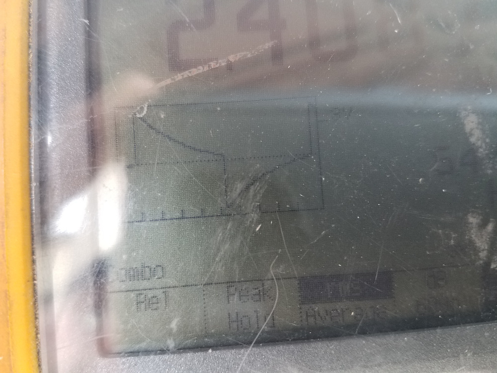
Third, with the engine off and I rotate the crankshaft, the cam signal transitions from 5 volts to zero and back to 5 volts. Without the engine running, I do not get the negative 5 volt wave cycle. See attached. This is the cam signal, running at idle.
Thanks in advance for any suggestions!
Geoff
Please Log in or Create an account to join the conversation.
- John Curtis
-
- Offline
- Platinum Member
-

- Posts: 345
- Thank you received: 111
Can you extend your time base and check if there is noise in the signal?
Making Pressure Differential Sensors (PDA Sensors) for pressure pulse diagnostics.
Currently servicing Central Texas.
Please Log in or Create an account to join the conversation.
- cfiigep
-
Topic Author
- Offline
- New Member
-
- Posts: 8
- Thank you received: 0
Yeah, it's a hall effect switch. When I manually turn the crank with the key on, it toggles from 5 volts to .1 volt. High and low. It never drops to minus 5 like it does when it's running. Not sure why.
Geoff
Please Log in or Create an account to join the conversation.
- cfiigep
-
Topic Author
- Offline
- New Member
-
- Posts: 8
- Thank you received: 0
I just borrowed the Fluke meter, and am not that familiar with it. I've tried to expand the time base, but the only option I could see was to manually change the amplitude, but not the time base. I'll screw with it some more and see if I can change the time base.
Geoff
Please Log in or Create an account to join the conversation.
- jreardon
-
- Offline
- Platinum Member
-
- Posts: 521
- Thank you received: 198
Chase down that sensor ground! You're right, the Black/Light Blue wire is sensor ground from computer. Same color wire goes to CAM, ECT, IAT, MAP, CKP, O2, TPS. Are you reading ground at the sensors but you're reading battery voltage at the computer? Something doesn't add up. Try jumping this wire to ground with a test light (just to be safe) connected to battery negative.
not sure how accurate the locations are: i.imgur.com/z8oJZAC.jpg
Please Log in or Create an account to join the conversation.
- cfiigep
-
Topic Author
- Offline
- New Member
-
- Posts: 8
- Thank you received: 0
I have good ground on the ground wire. It's the 5 volt wire where I have battery voltage. At least, the Dodge service manual says it's supposed to be 5 volts on the violet/white wire. But I have ground on the black/light blue wire. I am referencing all my voltages and waveforms from the sensor ground black/light blue wire. I don't know enough about the system to know if sensor ground is the same potential as battery ground. I thought the sensor ground might be a virtual ground within the computer, if there are supposed to be any bipolar voltages where sensor ground is NOT battery ground.
Thanks for the help!
I have ordered a cam sensor to install, since it was cheap and I don't think the waveform looks right. Plus, I am getting good logic signals from the cam sensor - 5 volts and 0.1 volts - when I slowly move the crank. This tells me it should be a square wave waveform - 5 volts and .1 volts - with the engine running at idle. Similar to the crank signal. But as you can see from the attached picture, it isn't. It's swinging plus 5 to minus 5, and it's anything but a square wave. It should drop immediately back to .1 or near zero, and the transition time is far too long.
The battery voltage on the violet/white wire is what confuses me. If the cam sensor is supposed to be bipolar 5, then it makes sense for the sensor ground to be a virtual ground. But Paul is pretty clear in his videos that Chrysler is a pull down circuit that is either at 5 volts or ground. And that the supply voltage to the sensors (not the signal voltage) is also 5 volts, and that nothing is supposed to go below ground potential. This would be basic TTL logic, with the slight voltage above ground with the transistor conducting being the voltage drop across the emitter/collector junction.
Can anyone tell me if the tach gets its signal from the cam sensor, or the crank sensor? The Dodge wiring diagram isn't clear where that's coming from, other than generated in the PCM.
Geoff
Please Log in or Create an account to join the conversation.
- jreardon
-
- Offline
- Platinum Member
-
- Posts: 521
- Thank you received: 198
Please Log in or Create an account to join the conversation.
- jreardon
-
- Offline
- Platinum Member
-
- Posts: 521
- Thank you received: 198
When you turn the CMP slowly, the signal seems okay?
Following the purple highlight that must mean you have battery voltage at the TPS: i.imgur.com/qkyEwpu.jpg
Short of cutting the 5v wire off at the PCM, to find out if this voltage is coming out of the PCM, got any ideas about that? I mean, if you can hook up your old computer and the 5v is 5v, that alone should tell you the computer is faulty.
Please Log in or Create an account to join the conversation.
- cfiigep
-
Topic Author
- Offline
- New Member
-
- Posts: 8
- Thank you received: 0
I tossed the old computer. The supplier didn't want it as a core, and I thought the problem was fixed initially. So the old computer is gone, and I can't A/B compare it.
The can and crank signals both go into the A port of the PCM. They both get supply voltage and ground from this connector. While both the Dodge manual and Paul say this is supposed to be 5 volts, and I am seeing battery voltage on this wire, the crank sensor is providing me a correct square wave regardless. Since the cam and crank sensors are functionally identical hall effect switches, the cam sensor should also be providing me a pull-down signal from 5 volts to ground. Which it does, when I pull the crank through by hand. But it won't track the high and low machined surface of the cam wheel dynamically.
Ok. Let's say Dodge decided to do something different on the V10, and used a different signal convention for the cam sensor. Plus and minus 5 volts, instead of 5 and 0. Which explains the 12 volts on the supply wire. But that's not what the Dodge manual says, and NONE of Paul's videos ever mentions this. Plus, from a design standpoint this makes no sense. But for argument, let's say it is. The damn signal still should be a square wave, with sharp transitions from one logic state to another. Not the F'ed up waveform I am seeing on the cam sense line.
Without the scope, I would not have seen this. Reading the DC voltages on the cam sensor slowly says it should work fine. But that sensor will not track the cam wheel in real time.
I'll have the new cam sensor in a few days, and let you know what I find. I still need to resolve the 12 volts versus 5 volts on the supply wire, but I have more than one problem here, I think.
We still use magnetos on piston aircraft engines for a reason, guys. Yeah, all this computer controlled stuff is very cool, but ya know, it's hard to screw up a set of points, a coil and a rotating magnet.
Thoughts?
Please Log in or Create an account to join the conversation.
- jreardon
-
- Offline
- Platinum Member
-
- Posts: 521
- Thank you received: 198
Please Log in or Create an account to join the conversation.
- guafa
-
- Offline
- Platinum Member
-
- Posts: 477
- Thank you received: 80
Maybe battery voltage on that sensor is killing it.
I would try first to power the new sensor with 5v. If 5v is not enough, it simply won't work.
Please Log in or Create an account to join the conversation.
- cfiigep
-
Topic Author
- Offline
- New Member
-
- Posts: 8
- Thank you received: 0
Please Log in or Create an account to join the conversation.
- cfiigep
-
Topic Author
- Offline
- New Member
-
- Posts: 8
- Thank you received: 0
With the ASD relay jumpered, the truck ran fine with just a slight hiccup from time to time during normal driving.
I purchased a set of better spiking clip leads, and found that the distorted wave form on the cam sensor was a result of a poor connection I had tried by spiking the wire with a pin. With the proper leads, the square wave looked fine. Both the cam and crank sensor signals were fine.
The intermittency was difficult to find, because everything looked fine. But the extended set of trouble codes kept showing crank sensor.
I finally got the engine to stall and stay stalled for a moment. It would crank, but not start. The cam signal remained fine, but the crank signal went flat line. In about 3 seconds of cranking, the crank signal returned and the engine restarted.
Ok, this points a finger at the crank sensor. However, back to my original discrepancy. The engine was only running on 8 cylinders, not 10. I had no spark on the numbers 1 and 6 cylinders. I replaced the PCM, and spark returned to those cylinders. But I never had the stalling issue until I replaced the PCM. Since you cannot buy a new PCM, I got one from an overhauler, Flagship One in New York.
I have found a source for a new old stock crank sensor, not too expensive, and have ordered it. By replacing the sensor, it will eliminate that as a possibility. Because while this appears to be a sensor issue, I cannot get it to hard fail long enough to see if I am losing the signal voltage out of the PCM.
I do not have the old PCM, I trashed it after I thought the bad spark issue was fixed. The stalling issue developed a few days later.
Side note. The truck stalled while driving, and would not restart. My thought was the fuel pump, and I replaced that. The truck started and ran on 8 cylinders. However, the pump may have been fine all along, and after cooling down, the engine restarted with the new fuel pump. This may have been a crank sensor all along. I never checked the codes before I replaced the pump, because I was certain it was the pump. Perhaps not.
If anyone has any thoughts or other suggestions, please share.
Geoff
Please Log in or Create an account to join the conversation.