O2 bias voltage cannot be pulled to ground
- keosintal
-
 Topic Author
- Offline
- New Member
-

- Posts: 7
- Thank you received: 5
Please Log in or Create an account to join the conversation.
- chief eaglebear
-
- Offline
- Platinum Member
-

- Posts: 340
- Thank you received: 70
Please Log in or Create an account to join the conversation.
- Tyler
-

- Offline
- Moderator
-

- Full time HACK since 2012
- Posts: 6115
- Thank you received: 1539
Is it possible you're looking at an air/fuel ratio sensor?
Please Log in or Create an account to join the conversation.
- keosintal
-
Topic Author
- Offline
- New Member
-
- Posts: 7
- Thank you received: 5
Tyler wrote: Toyota car/engine?
Toyota branded engine but designed by Daihatsu. The car it's in is neither of them.
Tyler wrote: Is it possible you're looking at an air/fuel ratio sensor?
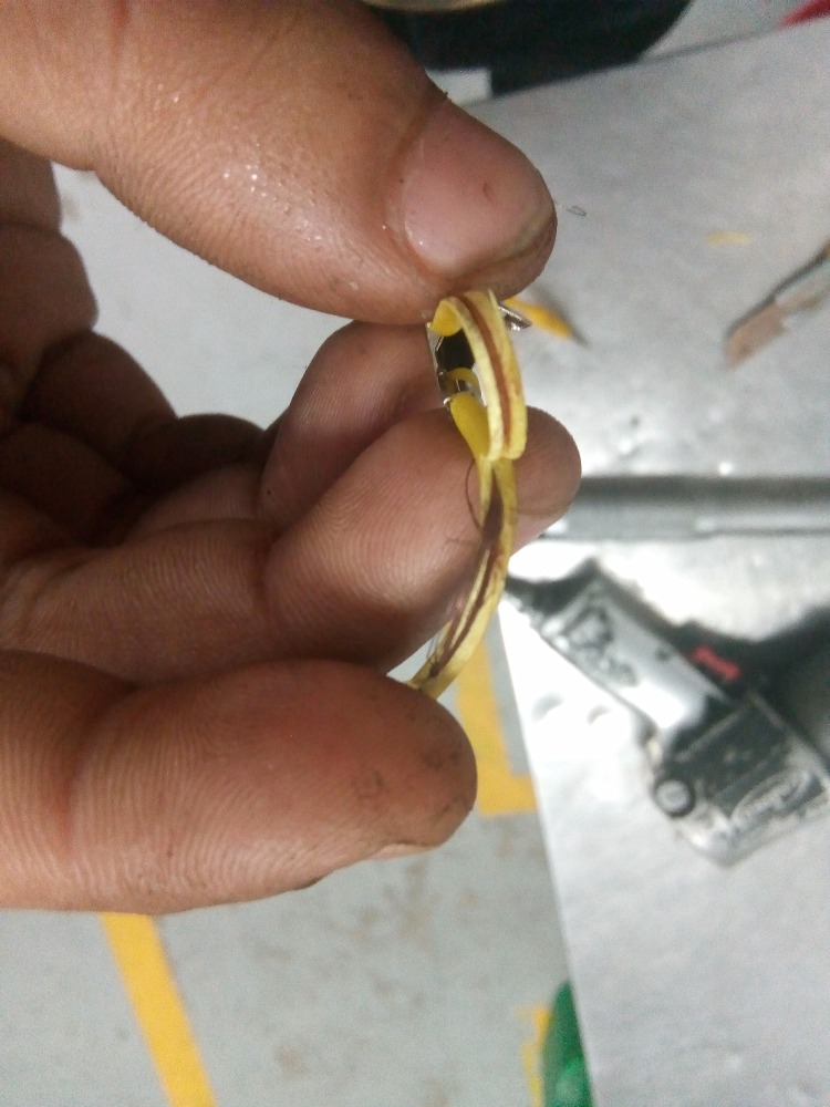
I can't say for sure. It has 4 wires with color pattern similar to heated O2. White, blue and 2 black wires.
I've tested 4 wires upstream on 2NR-VE with exact same color wires but the blue and white wire shows 3.3V and 2.9V respectively so I highly suspect that it's an air fuel sensor.
This 1KR-VE shows much lower voltage so I'm skeptical that it's a wideband, but I can't pull this signal to ground with my jumper.
When sensor is connected, my scan tool is showing the output voltage but when I disconnect it, the number change to 470mV.
Please Log in or Create an account to join the conversation.
- Tyler
-
- Offline
- Moderator
-
- Full time HACK since 2012
- Posts: 6115
- Thank you received: 1539
keosintal wrote: Toyota branded engine but designed by Daihatsu. The car it's in is neither of them.
Gotcha. Thanks for the clarification!
I've tested 4 wires upstream on 2NR-VE with exact same color wires but the blue and white wire shows 3.3V and 2.9V respectively so I highly suspect that it's an air fuel sensor.
Definitely an air/fuel sensor. Classic Toyota voltages.
This 1KR-VE shows much lower voltage so I'm skeptical that it's a wideband, but I can't pull this signal to ground with my jumper.
When sensor is connected, my scan tool is showing the output voltage but when I disconnect it, the number change to 470mV.
Just curious, what was the output voltage with the sensor connected? Also, could you check voltages on all four wires, disconnected? Might give a better picture of sensor design.
Also, do any codes set when you have that signal wire shorted to ground? If it's some kind of air/fuel sensor, then they're usually monitored for shorts, and should set some kind of P1XXX or P2XXX code.
Please Log in or Create an account to join the conversation.
- keosintal
-
Topic Author
- Offline
- New Member
-
- Posts: 7
- Thank you received: 5
What is it that I'm looking at? Is it some kind of negative/ground bias?Tyler wrote: Definitely an air/fuel sensor. Classic Toyota voltages.
Just curious, what was the output voltage with the sensor connected?
The 1KR-VE outputs 200-800mV like a typical O2, switching high and low.
One of black wire reads 12V with ignition on. Didn't try it with key off. The other black reads very low voltage, close to ground, the white wire reads 470mV (disconnected, harness side), while the blue reads low mV.Also, could you check voltages on all four wires, disconnected? Might give a better picture of sensor design.
Also, do any codes set when you have that signal wire shorted to ground? If it's some kind of air/fuel sensor, then they're usually monitored for shorts, and should set some kind of P1XXX or P2XXX code.
I only try it with KOEO, and it did not sets any DTC.
Please Log in or Create an account to join the conversation.
- jreardon
-
- Offline
- Platinum Member
-
- Posts: 521
- Thank you received: 198
This is my crude illustration of hookup. If the ground is good there's no way your meter is reading 470mV

.
Please Log in or Create an account to join the conversation.
- Tyler
-
- Offline
- Moderator
-
- Full time HACK since 2012
- Posts: 6115
- Thank you received: 1539
keosintal wrote: What is it that I'm looking at? Is it some kind of negative/ground bias?
Eh, kinda? :silly: I'm not sure I'd classify it as a bias, necessarily, just integral to how the circuitry inside the PCM detects current flow changes across the sensor itself.
I only try it with KOEO, and it did not sets any DTC.
Gotcha. I like jreardon's suggestion to retry grounding the circuit. It should be pulling down. :huh:
Please Log in or Create an account to join the conversation.
- keosintal
-
Topic Author
- Offline
- New Member
-
- Posts: 7
- Thank you received: 5
1. The 4 wires are actually 2 whites, black and gray. All measurements are made with sensor unplugged at the harness side with key on and negative DVOM lead connected to ground.
2. One of the white wire reads battery voltage and the other reads 2-4V (forgot the exact number), not close to 0 like I previously mentioned.
3. The black wire reads 450mV (455mV on the scan tool WITHOUT the DVOM in place), not 470mV, and the gray wire shows 3.8mV.
The reason I can't pull this bias on signal wire before is probably caused by my defective jumper wire. I use a different jumper the second time and it pulls the bias immediately. Then I decide to test my jumper for open and discover that it has a resistance of 1.4 Mega Ohms.
Not really a concern, but why did the heater ground reads 2-4V?
Thanks to Tyler and jreardon for assistance. I've learned something from my mistake and I hope everyone did too
")
Please Log in or Create an account to join the conversation.
- keosintal
-
Topic Author
- Offline
- New Member
-
- Posts: 7
- Thank you received: 5
Please Log in or Create an account to join the conversation.
- jreardon
-
- Offline
- Platinum Member
-
- Posts: 521
- Thank you received: 198
As for why the heater is reading that, i'm not so sure but Paul explains it better:
I guess it's preferable to do heater test with it plugged in otherwise it may set a dtc and just not turn on the heater anymore.
Please Log in or Create an account to join the conversation.