02 WRX, Front AFR sensor plugged in = misfires on all cylinders
- lottadro
-
 Topic Author
- Offline
- New Member
-

- Posts: 15
- Thank you received: 1
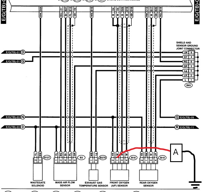
I have done a lot of testing between the ECM and front o2 sensor. What I have found is at the pins for the heater circuit ground (D4, D5), the ECM is not commanding them to ground. The FSM calls for a voltage of 0-1.0Vs with Key On Engine Off (KOEO), I am seeing 11.8Vs. I have tested the ECMs grounding pins (D8, D9) and the resistance was fine.
Additionally, I have a thread going on at NASIOC, where a few of us have been trying to come up with an answer, so far we are stumped. I have three o2 sensors I have tried in there, nothing changes, either OEM Subaru or Denso (whom makes the OEM part). I have also tried a spare ECM, and the problem persists. I have cleaned all the engine grounds. I replaced the spark plugs.
Please help me with this, I need this car for longer trips to school I have been fighting this thing since last September. You guys are my last shot.
forums.nasioc.com/forums/showthread.php?t=2900451
ken-gilbert.com/wrx/mans/7%20-%20WIRING.PDF
ken-gilbert.com/wrx/mans/3%20-%20DOHC%20ENGINE.PDF
Please Log in or Create an account to join the conversation.
- guafa
-
- Offline
- Platinum Member
-

- Posts: 477
- Thank you received: 80
According to your description, O2 sensor is not getting enough temperature to work properly.
It seems you have a heater driver issue. Have you tried to manually ground heater and see if idle improves?
Please Log in or Create an account to join the conversation.
- lottadro
-
Topic Author
- Offline
- New Member
-
- Posts: 15
- Thank you received: 1
No I have not tried to manually ground. Where would you suggest I add the grounds?
I guess I could back probe a wire directly from the sensor's bulkhead connector, running the wire to chassis ground.
Please Log in or Create an account to join the conversation.
- guafa
-
- Offline
- Platinum Member
-
- Posts: 477
- Thank you received: 80
Make completely sure is ground pin where you are. Otherwise if you ground heater power, you will blow a fuse or something else (general speaking).
Please Log in or Create an account to join the conversation.
- guafa
-
- Offline
- Platinum Member
-
- Posts: 477
- Thank you received: 80
Please Log in or Create an account to join the conversation.
- lottadro
-
Topic Author
- Offline
- New Member
-
- Posts: 15
- Thank you received: 1
I checked voltage on this new ground and it read within spec. .5V.
However, starting the car gave me the p0031 code, heater circuit low. I removed the ground and back probed at ECM connector D4 D5 again, and started car, during operation the pins showed between 7-8Vs. However the idle cleared up, my AFRs were not hunting all over the place. Additionally, a new code appeared p1139, heater circuit not within range. I am not sure what to make of this bizarre situation.
Please Log in or Create an account to join the conversation.
- Tyler
-

- Offline
- Moderator
-

- Full time HACK since 2012
- Posts: 6124
- Thank you received: 1541
In my experience, when this generation of Suby has a heater fault, it'll code, refuse to energize the heater, and run in open loop. This makes me think that the heater circuit behavior is a symptom of the problem, and not the problem itself.

I like guafa's suggestion about manually fielding the stock AFR sensor heater. As an alternative, you can also use the ammeter function in your multimeter to act as both a fused jumper wire AND measure the current of the circuit. I'd expect one amp of current, likely more if the sensor is cold. If you see good current flow, then you know the heater and the wiring is good.
")
As noted, double check which wire you're grounding. Isolate the ECM if you have any concerns.
Please Log in or Create an account to join the conversation.
- lottadro
-
Topic Author
- Offline
- New Member
-
- Posts: 15
- Thank you received: 1
Recently when I had that ground manual inserted at front bulkhead connect at AFR sensor, I was getting p1139 and p1130. I went through the diagnostic steps outlined in the FSM for both of those which ended by saying swap out front AFR sensor.
Proceeded to do so, and am back to square one of rough idle and misfiring. Additionally, a torrential down pour started along with thunder. So, today seems to be shot for working on it anymore.
Also I havent had the rear o2 in for a while. The wideband does show swings to lean when it misfires though.
This folder contains both a video and image related to both plugged and unplugged and are labeled accordingly, the image shows the codes I am pulling corresponding to the state of the sensor.
drive.google.com/drive/u/0/folders/1Kkgw...Hgwr_3qSxvY4bXfv0Xdk
Please Log in or Create an account to join the conversation.
- guafa
-
- Offline
- Platinum Member
-
- Posts: 477
- Thank you received: 80
At this point o2 heater manually ground, was a test to know if idle and pcm idle control improved (like you said happened). It's not a fixing. I would say those codes could be ignore for a while and stay focus on what Tyler suggested (which takes you to root cause).
Why did you change the first O2 sensor?
Please Log in or Create an account to join the conversation.
- Tyler
-
- Offline
- Moderator
-
- Full time HACK since 2012
- Posts: 6124
- Thank you received: 1541
lottadro wrote: Ok, something bizarre happened. I added the ground from the bulkhead connector at the sensor.
I checked voltage on this new ground and it read within spec. .5V.
However, starting the car gave me the p0031 code, heater circuit low. I removed the ground and back probed at ECM connector D4 D5 again, and started car, during operation the pins showed between 7-8Vs. However the idle cleared up, my AFRs were not hunting all over the place. Additionally, a new code appeared p1139, heater circuit not within range. I am not sure what to make of this bizarre situation.
Wow, didn't expect that. :ohmy: So as of right now, the mixture is happy and it idles smoothly?
Which connector did you add the ground at, specifically? At the four pin AFR connector? Again, I'd be very interested to measure the current draw of that circuit with your ammeter. I can illustrate this on the wiring diagram if needed. That'll tell us a lot about the wiring integrity under load.
Also, I got to thinking about this:
The FSM calls for a voltage of 0-1.0Vs with Key On Engine Off (KOEO), I am seeing 11.8Vs. I have tested the ECMs grounding pins (D8, D9) and the resistance was fine.
This seems entirely backwards to me. :silly: AFR heaters are almost never run KOEO, only with the engine running. That means the voltage readings you took are good. I think you're looking at an FSM misprint.
Please Log in or Create an account to join the conversation.
- lottadro
-
Topic Author
- Offline
- New Member
-
- Posts: 15
- Thank you received: 1
Taylor, yeah, I didnt expect that either and was pretty baffled until I assumed that ECM was pushing the car in to open loop, stabilizing the AFRs again. I ground by back-probe at B18, the front bulkhead harness side of the 4 pin sensor connector, Pin 1, which is the negative lead on the heater circuit going to ECM pins D4 D5.
I dont believe I have a good enough DMM for this process of using the ammeter. I'll have to purchase a better one, mine only reads up to 200mA and does not have a 10 amp fuse. If you wouldn't mind illustrating, I'd really appreciate it. Afterwards, I'll run the tests you want with the new DMM when it arrives.
Finally, I believe that the D4 D5 pins should have 0-1.0Vs even at idle, therefore my reading of 7-8vs would still be high, no? If it were a misprint that would seem to invalidate the diagnostic steps for p0031. I'm dont mean to second guess you here, and I hope I am wrong, but it doesnt seem logical to me.
Please Log in or Create an account to join the conversation.
- guafa
-
- Offline
- Platinum Member
-
- Posts: 477
- Thank you received: 80
If idle improved once you manually heated O2 sensor. We assume pcm is in closed loop, can't we?
When you manually grounded o2 heater, you changed current flow passing through heater driver current sensor. That's the reason for those codes. Does it make sense?
I'm trying to give us direction.
Please Log in or Create an account to join the conversation.
- Tyler
-
- Offline
- Moderator
-
- Full time HACK since 2012
- Posts: 6124
- Thank you received: 1541
lottadro wrote: I dont believe I have a good enough DMM for this process of using the ammeter. I'll have to purchase a better one, mine only reads up to 200mA and does not have a 10 amp fuse.
Ah, gotcha.
If you haven't already ordered one, there's a couple suggestions I could make. The Owon B35T is my personal favorite. 90% of a Fluke meter functionality, awesome durability, fraction of the cost:www.amazon.com/OWON-Multimeter-Measureme...ording/dp/B01C3IQDE8
The Autel AL539B is also amazing value - scanner, battery tester AND multimeter:
www.amazon.com/Autel-AL539B-Scanner-Star...rging/dp/B079GXRV1M/
If you wouldn't mind illustrating, I'd really appreciate it. Afterwards, I'll run the tests you want with the new DMM when it arrives.
Pretty much exactly what you've been doing, except the meter will measure the current draw for you.
Finally, I believe that the D4 D5 pins should have 0-1.0Vs even at idle, therefore my reading of 7-8vs would still be high, no? If it were a misprint that would seem to invalidate the diagnostic steps for p0031. I'm dont mean to second guess you here, and I hope I am wrong, but it doesnt seem logical to me.
Nah don't worry! To clarify, I think you should definitely get some kind of reading lower than B+ at idle, especially with the sensor cold. But with just the key on but the engine not running, a reading of B+ makes sense - to me, anyway. :silly:
Your reading of 7-8V also makes sense to me, as the PCM will pulse width control the heater ground once the sensor is hot and operating. The actual voltage is switching from 0-12V, but the meter averages that out to the 7-8V you saw. That reading makes me more confident in the PCM's ability to control the heater.
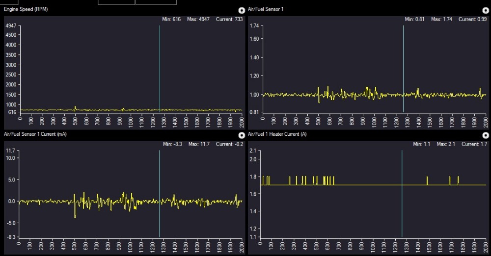
For whatever it's worth, I went and dug up some known good data from another '02 WRX that got a Denso AFR sensor due to a failed heater. The data afterwards showed a typical current draw of around 1.7A at idle. That's processed data through the scanner, but still a good point of reference for your testing.
Please Log in or Create an account to join the conversation.
- lottadro
-
Topic Author
- Offline
- New Member
-
- Posts: 15
- Thank you received: 1
Are you thinking I need a new OEM Subaru sensor?
Please Log in or Create an account to join the conversation.
- Tyler
-
- Offline
- Moderator
-
- Full time HACK since 2012
- Posts: 6124
- Thank you received: 1541
If possible, redo the same test at the PCM connector itself. Pin D4 or D5. If you get thr same reading, you know the wiring is capable of supporting current flow.
I know you've done resistance testing on these wires, but I really prefer current testing over resistance testing. It's a much more dynamic test that stresses the circuit under working conditions.
If you get a good current reading at the ECM, and the P1130/P1139 remains, I'd suspect an OEM sensor is in order.
Please Log in or Create an account to join the conversation.
- lottadro
-
Topic Author
- Offline
- New Member
-
- Posts: 15
- Thank you received: 1
Just did the same test at D4 D5 at ECM, as well as Pin 1, all were 4.9-5.0 A. The codes I am reading now are p0032 and p0037.
I would like to note that before I do the amp test the car acts in the manner I described previously, rough idle and wacky vacuum. When I connect the leads of the amp tester, I initially read a lower amp around 3ish, it smooths everything out, rises to 5 amp but then pops the codes.
Please Log in or Create an account to join the conversation.
- guafa
-
- Offline
- Platinum Member
-
- Posts: 477
- Thank you received: 80
5 amps reading is happening because you are fully demanding O2 heater. There is not pwm control, neither current pulses.
Again, why is rough idle going away once you heat O2 sensor? I mean, could PCM giving the order to not heat sensor, but at the same time trying to control emissions?
Please Log in or Create an account to join the conversation.
- lottadro
-
Topic Author
- Offline
- New Member
-
- Posts: 15
- Thank you received: 1
The idle smooths out, wideband shows rich at 13s or so, this may or may not be safe mode engaged by ECM due to the fact that although the sensor is manually ground, it is not seeing the ground signal coming in on D4 D5 from pin 1. Therefore, the computer thinks the sensor is doneso (pun), and safe modes the car; it acts exactly the same if I were to just simply unplug the sensor completely.
Also, a thing to remember, I already tried a spare ECM in there, and that did not fix it. Wires check low for resistance. Power supply is B+ at the power pin (2) and main relay, and SBF-5 fuse. The grounding pins D8 D9 which ground the front and rear sensors check good with low resistance and continuity through the harness all the way to their engine ground on top of the intake manifold.
Its hard to believe both ECMs would have the exact same issue. It is possible, probable, my OEM sensor is borked. It is also possible the Denso, even though they are the producers of the OEM component, is not meeting this specific car's specs and it needs OEM (this has been noted in prior posts on NASIOC). However, I have found nothing that really matches what I am seeing in my case.
Is it also possible, even though from what I can tell from the wiring diagram the o2 sensors are pretty much in their own circuits, that there is another component/ sensor in the engine bay that is causing "noise" within the system? I don't know if that is a good direction to take because it opens the field wide open again. Is the closed loop issue only a symptom of the actual problem?
I really appreciate the both of you taking time to help me with this. Thanks.
Please Log in or Create an account to join the conversation.
- Tyler
-
- Offline
- Moderator
-
- Full time HACK since 2012
- Posts: 6124
- Thank you received: 1541
The 13:1 reading in open loop means the car is capable of supplying fuel, which suggests a skewed input. MAF is always a big one, so that'd be my first check.
We know the reading will be all over the place with the rough idle, so how about the g/s reading at hot idle with no electrical loads on in open loop? Also a reading from the MAP sensor KOEO. Should match barometric pressure.
Please Log in or Create an account to join the conversation.
- guafa
-
- Offline
- Platinum Member
-
- Posts: 477
- Thank you received: 80
To Tyler suggestions, i would add a PCM ground test. I know you tested ground resistance, but it's better a voltage drop test. Check voltage between battery (-) and PCM ground when engine running.
Please Log in or Create an account to join the conversation.