*** Restricting New Posts to SD Premium Members ONLY *** (09 May 2025)

Just made a new account? Can't post? Click above.

Help us help you. By posting the year, make, model and engine near the beginning of your help request, followed by the symptoms (no start, high idle, misfire etc.) Along with any prevalent Diagnostic Trouble Codes, aka DTCs, other forum members will be able to help you get to a solution more quickly and easily!

Trying to solve a reduced engine power problem, not sure what to do next

  • Giblu427
  • Giblu427's Avatar Topic Author
  • Offline
  • New Member
  • New Member
More
6 years 4 months ago #29184 by Giblu427
Working on my uncles work truck, he has a 2004 GMC Sierra 2500hd 4wd with the 8.1l vortec.His problem is it intermittently goes into reduced engine power. There’s no rhyme or reason for it, I could drive 200 miles no problem or back out of the driveway and go into REP mode. Hot, cold, rain, sun doesnt seem to make a difference. The hard set codes were p120, p220, p1516, and p2135. It has a new throttle body assembly, tps connector and harness , pedal assembly, tac module was swapped with a junkyard unit but made no difference so he threw the original one back on. He did the “throttle relearn procedure”. I say it that way because I’ve seen several different ones, he did the “idle 6 minutes, key off 60 seconds, rinse and repeat”. So what i’ve done so far is check current on all grounds. Found and replaced a burned up ground wire in the pedal harness (app3 low reference) checked,clean, and tightened all the grounds on the engine block and frame, all grounds are showing good current flow, continuity, 0 voltage drop and less than 1ohm resistance. The 5v references show a slight voltage drop of about 100 millivolts each, good continuity, less than 1 ohm of resistance. Same with the signal wires. However, the 5v reference wire and signal wire for tp2 is showing some weird stuff. With everything connected as normal and the key on engine off, tp2 signal is at 0.78v and the 5v reference is at 4.26v. With the harness disconnected from the throttle body and the key on 5v is showing 4.99v and the signal is at 4.91v, if I plug in the connector with the key still on it changes to 4.88v(5v reference) and 1.12v(signal). When I cycle the key off and back on with everything connected it goes back to the original readings (4.2v at reference, 0.78v signal). Tp1 connected and key on shows 4.88v(reference) and 1.14v(signal). Just out of curiosity i also jumped the connections for tp2 alone to the throttle body and it read 4.88v at reference and 1.12v signal. Did it with tp1 and showed 4.88v reference and 1.14v signal. I jumped them at the front of the connector and in the back with t-pins and got the same reading either way. Also I had the old throttle body laying around and plugged the harness in there and got the exact same readings. Also the battery is reading 12.2v and im sure it wouldnt hurt to charge it. I ordered a scan tool that can do throttle resets but until then what would my next step here? I have a wiring diagram attached and blue/black is tp2 5v reference, purple is the signal wire
Attachments:

Please Log in or Create an account to join the conversation.

  • Chad
  • Chad's Avatar
  • Offline
  • Moderator
  • Moderator
  • I am not a parts changer.
More
6 years 4 months ago #29185 by Chad

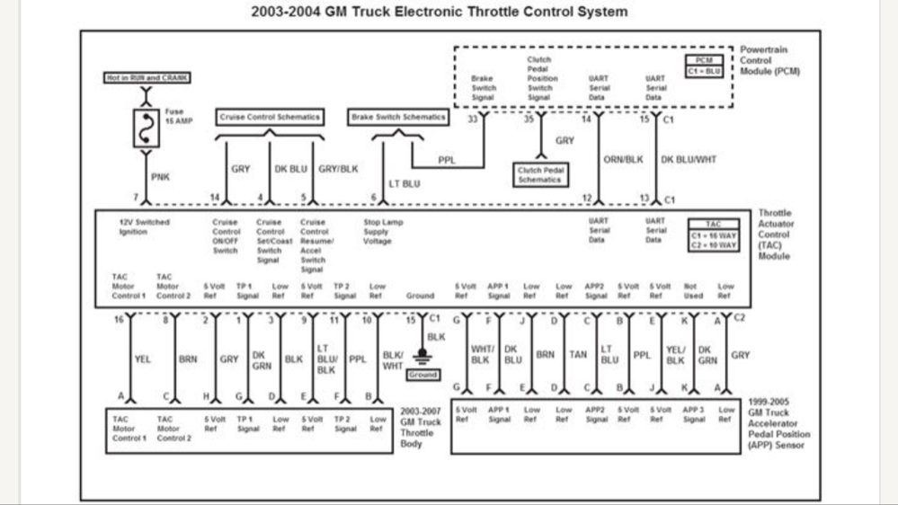
Giblu427 wrote: and the 5v reference is at 4.26v.


This is where I would be concentrating. Have you checked the voltage at BOTH ends of the wire?

"Knowledge is a weapon. Arm yourself, well, before going to do battle."
"Understanding a question is half an answer."

I have learned more by being wrong, than I have by being right. :-)

Please Log in or Create an account to join the conversation.

  • Giblu427
  • Giblu427's Avatar Topic Author
  • Offline
  • New Member
  • New Member
More
6 years 4 months ago #29192 by Giblu427
I wasnt able to back probe the connector to the tac module so i pierced it as close as I could to the connector and it reads the same 4.2v. But again if i unplug the tps connector and turn the key on it reads 4.99v at both ends as well.

Please Log in or Create an account to join the conversation.

  • Chad
  • Chad's Avatar
  • Offline
  • Moderator
  • Moderator
  • I am not a parts changer.
More
6 years 4 months ago #29209 by Chad
What is the Voltage (at the TAC) on the Pink wire at Pin 7? And, the BLK wire on Pin 15, while you are seeing the voltage drop on the 5v ref?

"Knowledge is a weapon. Arm yourself, well, before going to do battle."
"Understanding a question is half an answer."

I have learned more by being wrong, than I have by being right. :-)

Please Log in or Create an account to join the conversation.

  • Giblu427
  • Giblu427's Avatar Topic Author
  • Offline
  • New Member
  • New Member
More
6 years 4 months ago #29224 by Giblu427
Pink wire mimics battery voltage at the wire and at the fuse, I have a cheaper multimeter so it kept moving from 12.1 to 12.2v but the black ground wire was solid on 12.2v with my red lead on battery + and black lead at both the wire and on the bolt ( its runs to the back of one of the cylinder heads).

Please Log in or Create an account to join the conversation.

  • Chad
  • Chad's Avatar
  • Offline
  • Moderator
  • Moderator
  • I am not a parts changer.
More
6 years 4 months ago #29226 by Chad

Giblu427 wrote: but the black ground wire was solid on 12.2v with my red lead on battery + and black lead at both the wire and on the bolt ( its runs to the back of one of the cylinder heads).


Leave the black test lead connected to Battery (-). Touch the Red test lead to the Black ground wire on pin 15. (Yes, you are testing GROUND-to-GROUND).

A reading of more than 100mv ( 0.1 volt) would indicate a bad ground. Be sure to use the Negative battery post for your black test lead. Not the engine block.

"Knowledge is a weapon. Arm yourself, well, before going to do battle."
"Understanding a question is half an answer."

I have learned more by being wrong, than I have by being right. :-)
The following user(s) said Thank You: Andy.MacFadyen

Please Log in or Create an account to join the conversation.

  • Giblu427
  • Giblu427's Avatar Topic Author
  • Offline
  • New Member
  • New Member
More
6 years 4 months ago #29250 by Giblu427
Thanks, I will definitely go back and confirm that all the grounds are reading less than.1volts. Assuming they all check out ok, where else would I look? Its as if the 5v reference is being reset to 4.2v whenever the key is cycled.

Please Log in or Create an account to join the conversation.

More
5 years 9 months ago #35852 by Dowachuwant
Did you ever solve this? I have troubleshot everything you have mentioned and I'm in the same boat.

Please Log in or Create an account to join the conversation.

More
4 years 11 months ago #43690 by Dugy40
I am having same issue 2004 avalanche 5.3
Where’s pin 15? Is that on the tps plugin?

Please Log in or Create an account to join the conversation.

More
4 years 11 months ago #43691 by Dugy40
2004 avalanche 5.3. Where can I get a diagram of tps system? The one above is blurry. Thank you.

Please Log in or Create an account to join the conversation.

Time to create page: 0.436 seconds