2002 Dodge Durango, 4.7, No start, No bus message
- raballard@aol.com
-
 Topic Author
- Offline
- New Member
-

- Posts: 16
- Thank you received: 0
Please Log in or Create an account to join the conversation.
- Tyler
-

- Offline
- Moderator
-

- Full time HACK since 2012
- Posts: 6129
- Thank you received: 1545
Just so I'm clear, where exactly did you measure 5V on the PCI bus circuit? At the DLC? Just trying to get an idea about where you've done your testing so far.
I see that you've disconnected sensors, good move. Looking for a short, right? Even though disconnecting them didn't help, I'd still suggest checking the 5V reference circuit, just to make sure it's there. Given the no start and no communication, I'm gonna wager that it's gonna be MIA.
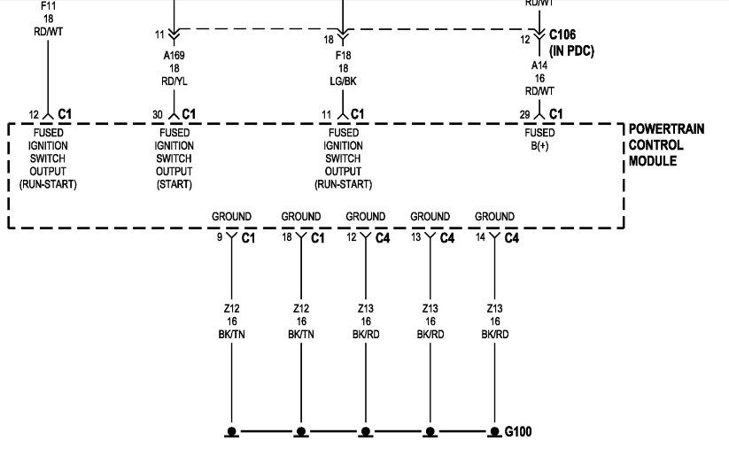
With the testing you've done so far, I think my next move would be to check powers and grounds at the PCM itself. Your multi meter will work perfectly for this, no scope required. It'd also be super easy to check fuses before digging the computer out. Be sure to check both fuse boxes, under the hood and under the dash.
Let us know how the 5V reference and fuse checks turn out, and we can go from there!
Please Log in or Create an account to join the conversation.
- raballard@aol.com
-
Topic Author
- Offline
- New Member
-
- Posts: 16
- Thank you received: 0
I had read various posts from other owners about shorted sensors. And they suggested unplugging each one by one. Power cycle the key to see if the No Bus message went away. Ran into another post about the various components on the PCI bus causing the same problem. So I unplugged each of those one by one too.
By using the RPM gauge on my code reader, I'm not getting any RPM indication while cranking. So I agree. Either the PCI bus is completely down, or the PCM is fried.
I'm sorry. I neglected to mention that I do have 12 volts on pins 2 and 22 at the black PCM connector. Pins 31 and 32 both appear to be good grounds. I have disconnected and cleaned every body ground that I've found so far. Even made a few of my own temporary grounds just using alligator clips directly to the battery.
Please Log in or Create an account to join the conversation.
- busjockey1..
-

- Offline
- New Member
-
- Posts: 17
- Thank you received: 0
The Diesel Nerd
Please Log in or Create an account to join the conversation.
- raballard@aol.com
-
Topic Author
- Offline
- New Member
-
- Posts: 16
- Thank you received: 0
Last I checked, I could not communicate with the PCM through my scanner. And everything was plugged in. My meter did not die, just showed 0 RPM while cranking.
I do not have a back probe. So when I was testing for power and ground at the PCM, the black connector was unplugged. All of the other sensors and components were plugged in.
Thanks again for your help.
Please Log in or Create an account to join the conversation.
- busjockey1..
-
- Offline
- New Member
-
- Posts: 17
- Thank you received: 0
The Diesel Nerd
Please Log in or Create an account to join the conversation.
- Tyler
-
- Offline
- Moderator
-
- Full time HACK since 2012
- Posts: 6129
- Thank you received: 1545
So I totally struck out on the 5V reference circuit, was totally expecting you to find none. Oops!
It's awesome that you've already done PCM power/ground checks, those were the exact pins that I was going to suggest testing on. busjockey is right, though, voltage drop testing with backprobes is the best way to be certain in these cases. Either that, or substitute a load for those wires using a tail light bulb.
5V ref is there, powers and grounds looking good, doesn't bode well for the PCM! Poking around on the BBB Industries site, I actually found a different power/ground diagram with some additional pins. Take this with a grain of salt, as I'm not positive that this is the correct diagram. Just don't want to miss anything before calling a module.
Thought about a Chrysler 8V CKP/CMP/VSS circuit, but the diagram says these hall effects use the 5V reference instead. Still, might be worth checking either the cam or the crank sensor for a reference voltage. Finding zero would suggest that there IS a separate reference circuit.
Please Log in or Create an account to join the conversation.
- raballard@aol.com
-
Topic Author
- Offline
- New Member
-
- Posts: 16
- Thank you received: 0
By back probing the MAP connector with everything plugged in. I've got 4.47 volts between pins 1 & 2. 5.17 between 1 & 3. and .72 between 2 & 3.
Please Log in or Create an account to join the conversation.
- Tyler
-
- Offline
- Moderator
-
- Full time HACK since 2012
- Posts: 6129
- Thank you received: 1545
I agree, the voltage drop you're seeing on pin #22 seems to indicate some kind of load on that circuit when plugged in, good stuff. The grounds are looking good, too.
I've never measured a 5V reference sensor that way that you did, between pins on the connector, but I think that all sounds right. Showing 5V between 1 and 3 would be going between reference and ground, .72V would be between signal and ground, and 4.47V would be between signal and 5V? Sorry, just putting that together in my head.
Calling a PCM is never easy... Are we missing anything?
Please Log in or Create an account to join the conversation.
- raballard@aol.com
-
Topic Author
- Offline
- New Member
-
- Posts: 16
- Thank you received: 0
What's a good source for PCM's?
Should I buy a rebuilt?
Or send this one in for rebuilding?
Please Log in or Create an account to join the conversation.
- Tyler
-
- Offline
- Moderator
-
- Full time HACK since 2012
- Posts: 6129
- Thank you received: 1545
raballard@aol.com wrote: What's a good source for PCM's?
Man, I wish I knew! Even the new or reman PCM's of this generation are known for problems. I'd be inclined to get it from a local parts store, so you have a human being to deal with, and some kind of warranty if your replacement computer has other problems.
I don't know that we're missing anything so far, but I'm happy to hear from anyone else following along if I've overlooked something. Wondering if it's worth taking the PCI bus wires out of the PCM connector and rechecking for communication, just to eliminate the network from the equation.
Please Log in or Create an account to join the conversation.
- Noah
-

- Offline
- Moderator
-
- Posts: 5065
- Thank you received: 1127
Last I checked, I could not communicate with the PCM through my scanner. And everything was plugged in. My meter did not die, just showed 0 RPM while cranking.
I'm still confused by this. I'm not nitpicking here, but if you can't communicate, what are you looking at for an RPM pid?
I may be biased, but I don;t have problem with used PCMs from the salvage yard. Sometimes a good used factory part is better than a brand new Made In China unit.
Please Log in or Create an account to join the conversation.
- Noah
-
- Offline
- Moderator
-
- Posts: 5065
- Thank you received: 1127
Attachment not found
Are you using a diagram or pinout to ID the pin numbers?
This would be disconnected, front probed....
I think...
definitely check the colors of the wires to be sure.
I've got 4.47 volts between pins 1 & 2. 5.17 between 1 & 3. and .72 between 2 & 3.
So with 1 being signal and 2 being sensor ground, 4.47v seems high, but plausible.
1 being signal and 3 being 5v supply 5.17v I cant quite make sense of that yet
2 being ground and 3 being 5v supply, .72v says red flag
Just check them all with the negative lead of your meter on the negative post of the battery, and if you think of it, post the readings with the wire colors please.
Please Log in or Create an account to join the conversation.
- Noah
-
- Offline
- Moderator
-
- Posts: 5065
- Thank you received: 1127
This is all I could get BusJockeyAlso could someone post a schematic of this Pci Bus system? I don't have one but if someone could post it I might be able to help with this. I have quite a bit of experience working with no Comm issues on Buses. This might be a little different, but the concepts still apply here.
Attachment not found
Please Log in or Create an account to join the conversation.
- raballard@aol.com
-
Topic Author
- Offline
- New Member
-
- Posts: 16
- Thank you received: 0
.72 on the orange/blue.
And the black does seem to be a good ground.
Please Log in or Create an account to join the conversation.
- Noah
-
- Offline
- Moderator
-
- Posts: 5065
- Thank you received: 1127
raballard@aol.com wrote: I've got 5.2 V on the orange wire.
.72 on the orange/blue.
And the black does seem to be a good ground.
OK, cool. That seems to be normal. I was confused by the way it was posted before, thanks for clearing that up.
Like Tyler mentioned before, it's never easy to call a PCM.
Probably won't help in this case, but I like to open them up and sniff around for that tell tale burned electrical component smell.
Do you have communication with any other module?
I like Tyler's idea here:
don't know that we're missing anything so far, but I'm happy to hear from anyone else following along if I've overlooked something. Wondering if it's worth taking the PCI bus wires out of the PCM connector and rechecking for communication, just to eliminate the network from the equation.
Please Log in or Create an account to join the conversation.
- raballard@aol.com
-
Topic Author
- Offline
- New Member
-
- Posts: 16
- Thank you received: 0
Remember all I have is a multi meter and an error code reader.
Please Log in or Create an account to join the conversation.
- busjockey1..
-
- Offline
- New Member
-
- Posts: 17
- Thank you received: 0
The Diesel Nerd
Please Log in or Create an account to join the conversation.
- raballard@aol.com
-
Topic Author
- Offline
- New Member
-
- Posts: 16
- Thank you received: 0
I've only got a multi meter and a code reader.
Please Log in or Create an account to join the conversation.
- busjockey1..
-
- Offline
- New Member
-
- Posts: 17
- Thank you received: 0
The Diesel Nerd
Please Log in or Create an account to join the conversation.