2018 Ford Escape SE 1.5L Ecoboost- Crank, No Start, No DTC
- aggiediesel01
-
 Topic Author
- Offline
- New Member
-

- Posts: 15
- Thank you received: 4
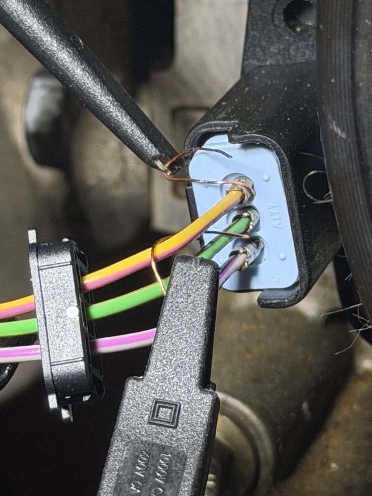
I'm really struggling to figure this one out. I've probably glossed over something or need to recheck some steps but I'm too close to the problem to make sense of this anymore so feel free to tell me what I need to go back and check. I've owned the car since August and it has been running fine until this happened. I've got pictures of my scope wave forms on my phone that I'll be editing into this post over the next hour or so if anyone reads this before then. I have a 4ch scope hooked to 10:1 ChA: CKP(Pin2 SigRTN, Pin3 CKP), 10:1 ChB: Fuel INJ1 (Pin2 INJ1, Gnd), 10:1 ChC: COP1 (Pin1 COP1A, GND), 10:1 ChD: CMP11 Intake (Pin2 CMP11, Pin1 SIGRTN), also using ChD with regular meter probes 1:1 to look for weird voltage spikes.
2018 Ford Escape 1.5L Ecoboost GTDI with a Crank but No Start and no DTC issue. This car was running and driving fine one day and the next; it cranks but will not start. I have the 2018 Ford manuals and wiring diagrams. I have worked through the 2018 PC_ED no DTC diagnostic tree down to the fuel injection system where now I'm recording measurements that conflict with the PC_ED but I don't have confidence that the manual is accurate here because there seems to be a slight conflict in the PC_ED between the Pin Point test A10 (maybe it's for non GTDI?) and Pin Point test DI 7 which calls for testing to observe different results than what I see.
I have already replaced the PCM and main engine wiring harness because I found them filled engine oil. That was discovered during the earlier section of the pinpoint tests and is detailed lower down.
PP Test DI #7 in the 2018 PC_ED says to check each leg of the injector connector for a short to voltage with the ignition switch on. When I check this by just disconnecting one injector I can measure 6.4VDC on pin1 (INJRTN) and .333VDC on Pin2 (INJ). If I disconnect all the injectors the voltage on the RTN circuits jumps to 11.8VDC and .333 on the supply circuit. If I connect all the injectors and back probe inj1 there is .55VDC with a 30ms spike to nearly 5V (ac+dc reads .84V).
The PP Test says that there should be no voltage present and I should repair the short to voltage but gives no indication of where the voltage might be coming from. I have not been able to find shorts to ground on any of the circuits and no shorts from the supply circuits to the return circuits. Also I find that the voltage on the injector circuits arrives as soon as a door is opened or the key is turned on (with the windows rolled down to reach in) and goes away about 45sec after the door is closed and or the ignition is turned off. This information might be a distraction to the issue at hand but it indicates to me that this voltage is related to the “wake up” signal sent to the PCM from the BCM. The fact that the voltage fluctuates based on how many injectors are plugged in makes me think it’s not a normal signal and maybe it’s coming from one of my other engine sensors that was wet with oil. I have disconnected each engine sensor and observed the same results, then I disconnected the entire engine wiring harness (except for the batt junction box plug) and observed the same results. After that I installed the old PCM on the wiring harness while it was completely disconnected and observed the same results.
Ford says I should measure no voltage on the injector circuit but there is a little bit and it has a 30ms spike, what does this mean? There are 2 coolant pumps down near the bottom of the engine that run during KOEO but I can’t think of any other rotating items that could be creating this, I have disconnected those and the spike remains.
Pic1
I have used the wiring diagrams to try to find every 12+ signal going to the PCM and measure it with a scope. I think I found all of them but I cannot find any source with a 30ms spike in it. I also probed a sensor that has VREF and that is steady at 5VDC with no ripple or spike. The PCM seems to be generating it and the old one did too.
It occurred to me that it could be coming from my battery charger but when I completely disconnected it the spike is still there.
I installed the same PCM revision that was in the old one but I think there is a newer one available. I didn’t want to add a variable to my problem yet but maybe it’s time?
Other items I’ve checked and observed:
It does stumble a little bit during the first couple cranking intervals but then it just cranks.
I have investigated the engine for base engine issues; I've verified the mechanical timing with the timing tool set (including pining the crankshaft, checking the CKP position, and the holding tool for cams). I have measured cylinder compression at 145, 145, 135, 140 (all plugs pulled but I didn’t block open the throttle plate).
Battery test shows 84% life and is fully charged while testing.
Throttle body checks out according to PP test.
Engine cranking speed w/ plugs is about ~240rpm, w/o plugs it’s 315rpm according to scope data.
CKP/CMP Sync PID shows positive in FORSCAN while cranking.
I have 4 new Motorcraft spark plugs and they all spark nice and bright blue from each of their coils. I changed the spark plugs b/c the ones in the car showed a bright orange spark even though they passed the KV gap test. The new plugs show a bright blue spark from each of the coils.
Fuel pressure, Low and High, the low pressure fuel system was verified at 95psi with a mechanical gauge, the high pressure fuel system is showing 1900psi in FORSCAN but I don’t have a gauge or way to verify that. The bleed down test results are a bit confusing to me; the low pressure side bleeds down during engine cranking as I expect it would, the high pressure side bleeds down a little and then stops bleeding down. With the LP fuel pump fuse pulled; HP Fuel pressure reads ~1900 (if I unplug the HP sensor the PCM reads about 4k psi) after 5+ cranking intervals it still shows over 1500psi, after a few more cranks it falls to about ~1400psi but I've never seen it lower after many cranks. If it goes into Dechoke while cranking does that mean it's not delivering anymore fuel and HP psi would stay steady?
Code History; there were no history codes. Unless there's some hidden memory somewhere that no one really talks about. I am using the paid/licensed version of FORSCAN so I should have access to every area of the diagnostic system and I don’t see any codes other than the ones that pop up when I disconnect a sensor and it shows “engine fault” or CEL on the driver info screen and then clears when I clear the codes.
When I got to PP Test DI:5 I pulled the PCM and Harness connectors and they were literally dripping with oil. I checked every sensor I could easily disconnect and many had oil in their connectors. Cleaned all the sensors I could reach and replaced both cam solenoids and one cam sensor (just because they weren't Ford). Because of the oil intrusion, the PCM and Engine Wiring Harness were replaced and reprogrammed using FORSCAN (made sure both harness grounds are making good continuity). PCM passes the on demand self-test, seems to communicate with other modules with no faults, shows matching module data to the old PCM and other modules, and the engine cranks and gives spark with all 3 keys that I have. I also found and checked the PID for START_ENABLED and that shows Enabled with each of my keys while cranking.
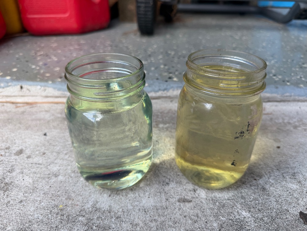
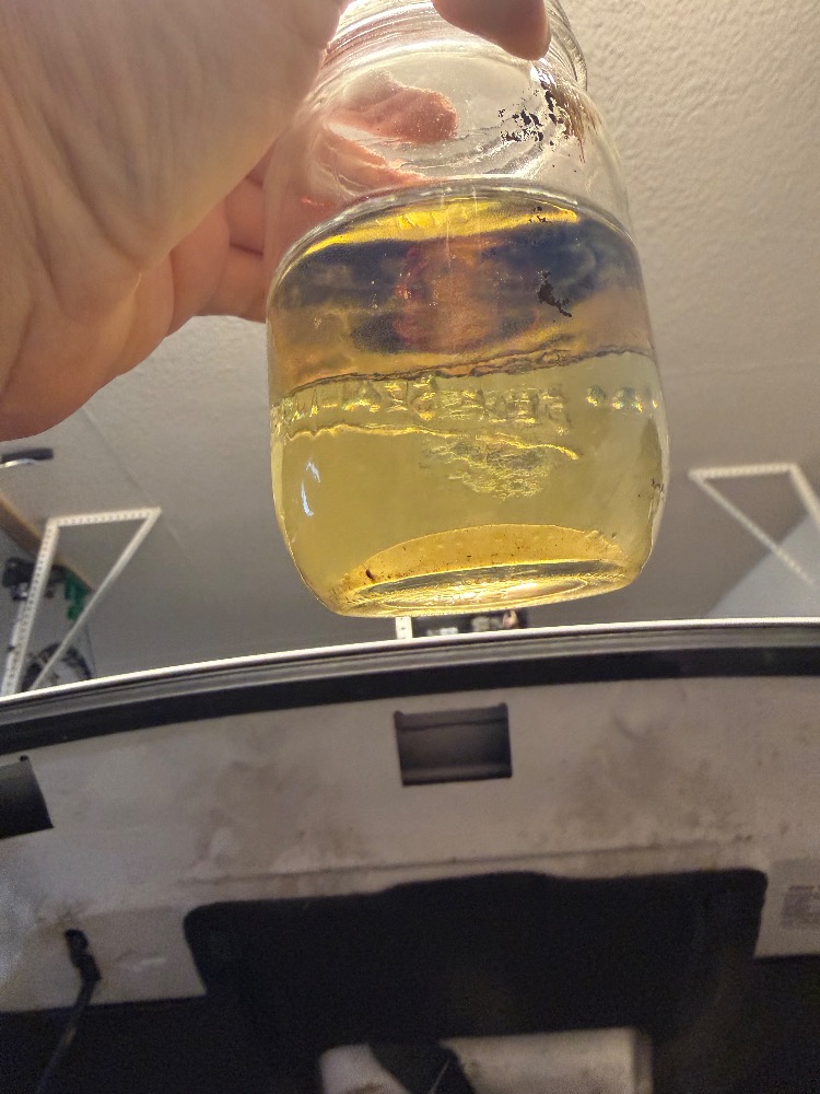
Checked the fuel condition, I didn’t observe any specific issue with it (filled with midgrade last fillup) but it was dark and a small amount of water settled out of a sample overnight so I siphoned the tank as low as I could get it and then I used the fuel pump to pump the tank out until it was pushing air out of the hose. Then I put 5gal of premium in and bleed the LP fuel line until it there was no air and reconnected it.
Other general information about the situation and questions I have:
I'm not sure if the FORSCAN reprogram does the parameter reset or not or but other than still not starting it seems to behave normally and I think that mostly has to do with PATS, am I wrong?
I don't think I can do the Neutral Profile Correction until the engine is running. Where do I go from here? What am I missing?Any thoughts or pointers would be greatly appreciated.The HP fuel sensor behavior seems odd to me, could that be another thing to poke at? What is normal behavior for the HP side when the LP isn't supplying fuel? How low should it read and how quickly should it drop?
Are there any important sensors that might be internally affected if oil was pumped into them?
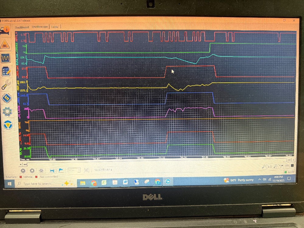
Take a look at the FORSCAN graphs of the cranking events if that gives any further understanding of what the engine is doing, or if there's another parameter I should be monitoring let me know. The graph with 2 cranking events shows me blipping the throttle during the second event just to see that it works. There is also an older graph that shows the camshaft sensors being monitored as well.
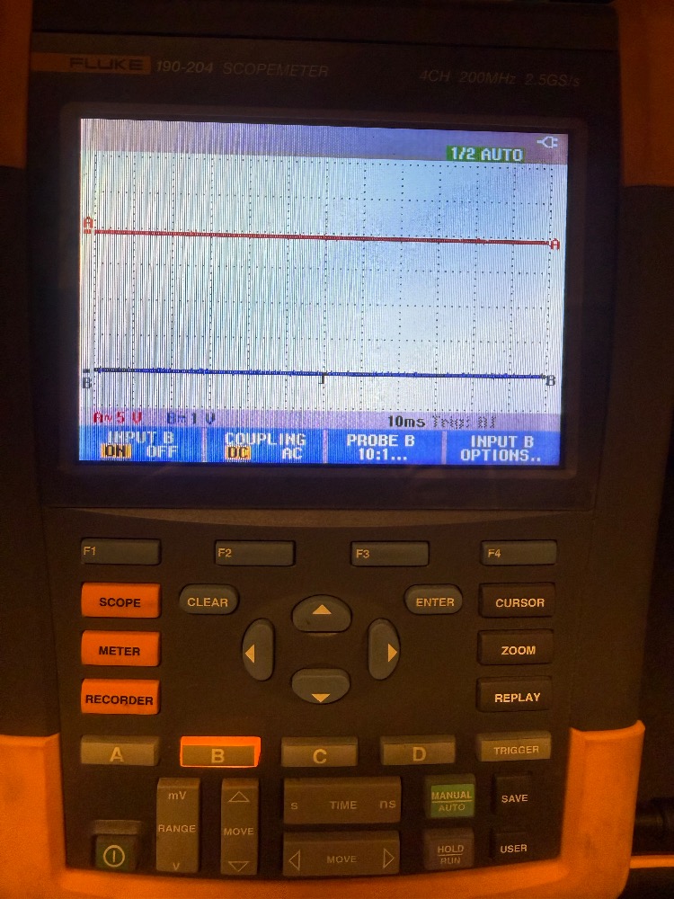
System at rest
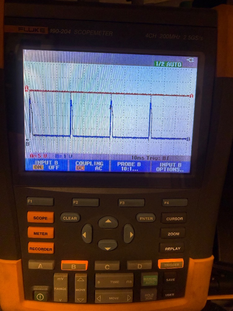
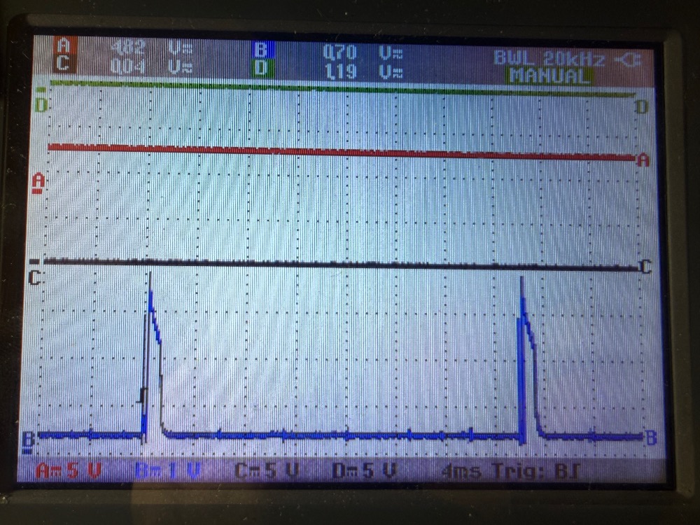
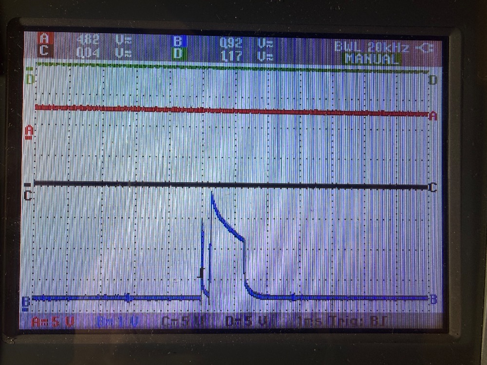
KOEO .5vdc offset on inj1 w/ 30ms ripple

When I turn the key off the ripple goes away but the offset remains for about 45sec which seems to be when the PCM shuts down as VREF goes away too.
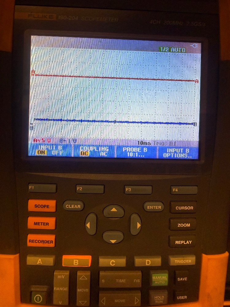
This is proving the battery charger isn’t contributing to it.
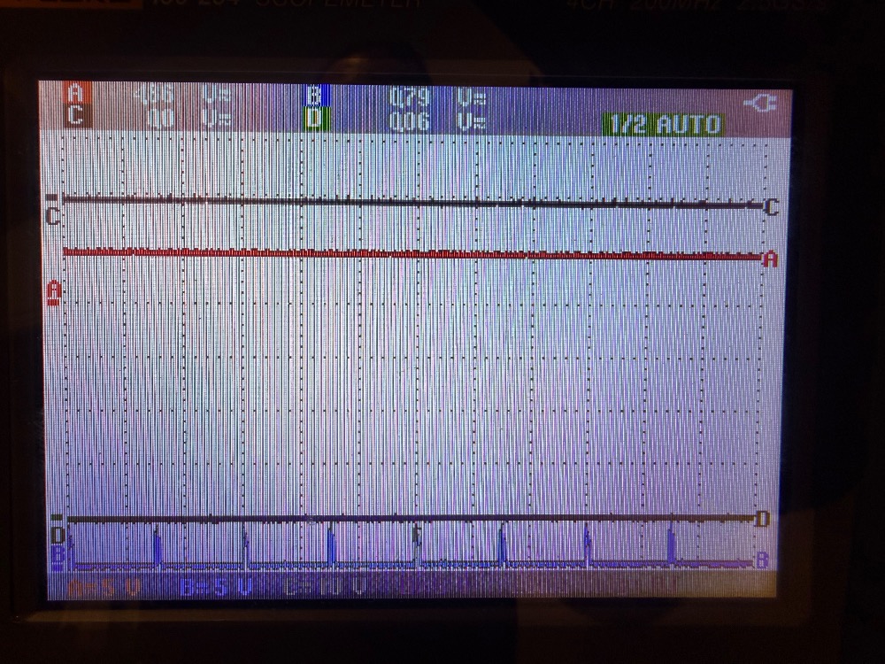
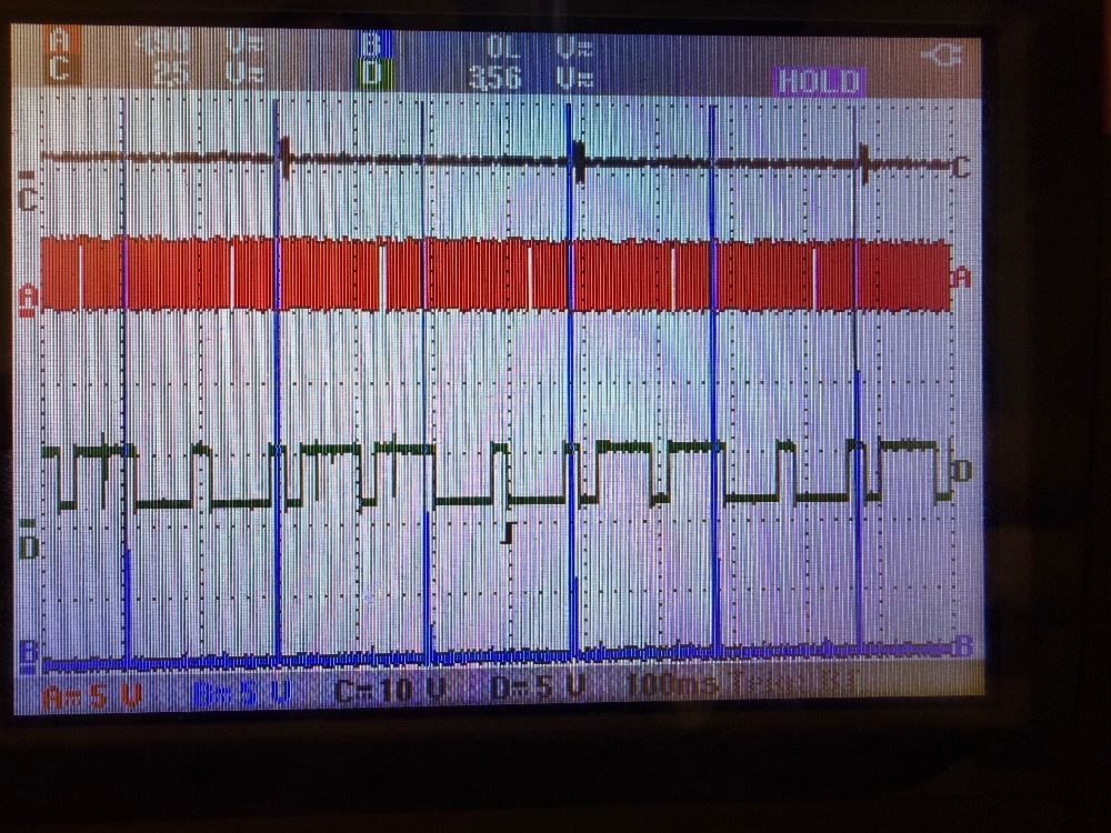
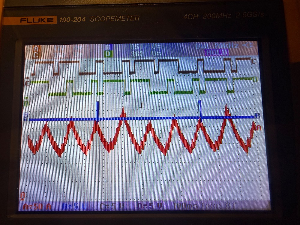
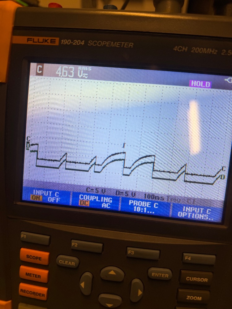
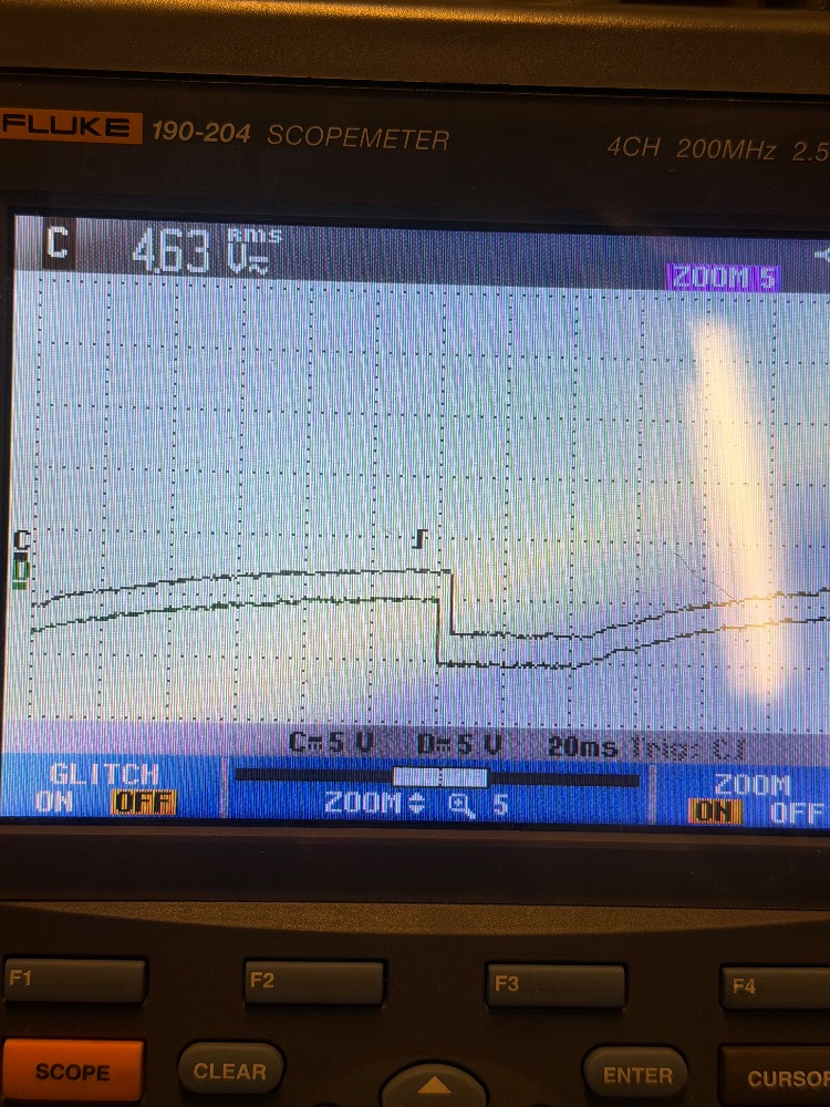
This is just the CKP and INJ1 to see if I was setting things up correctly. I really struggled getting the trigger to trigger on what I wanted to see. I’m still not getting enough of everything so any tips are appreciated.
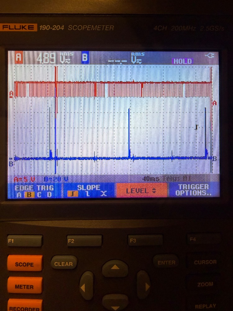
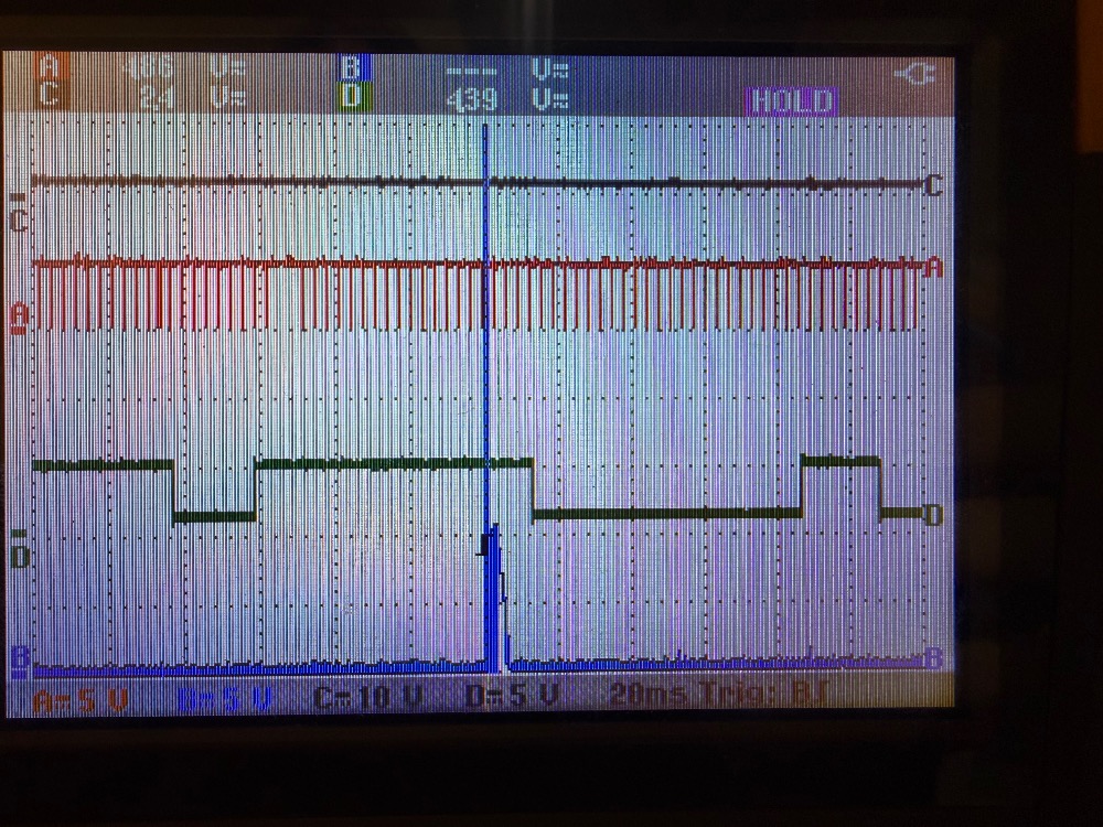
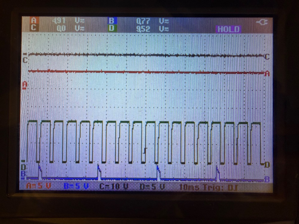
I can see there is a “missing tooth” that shows 360deg but why is the injector firing every cycle instead of every other?
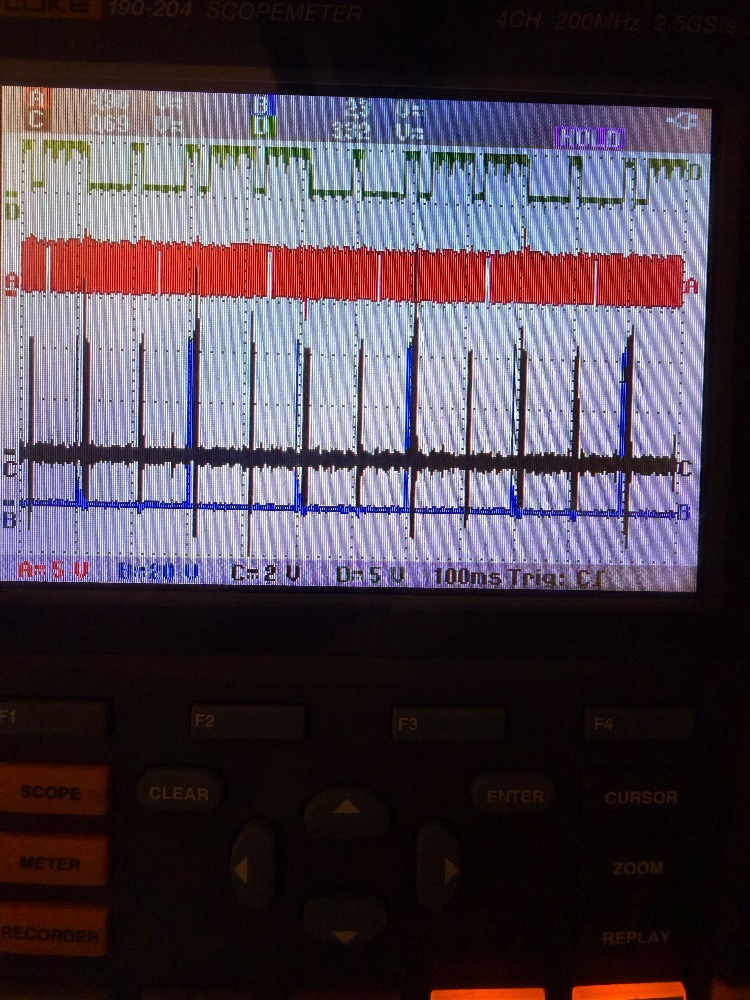
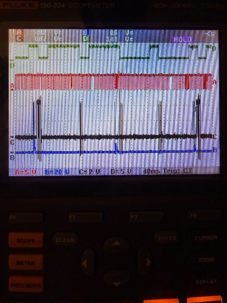
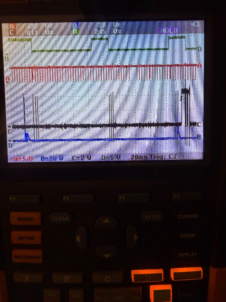
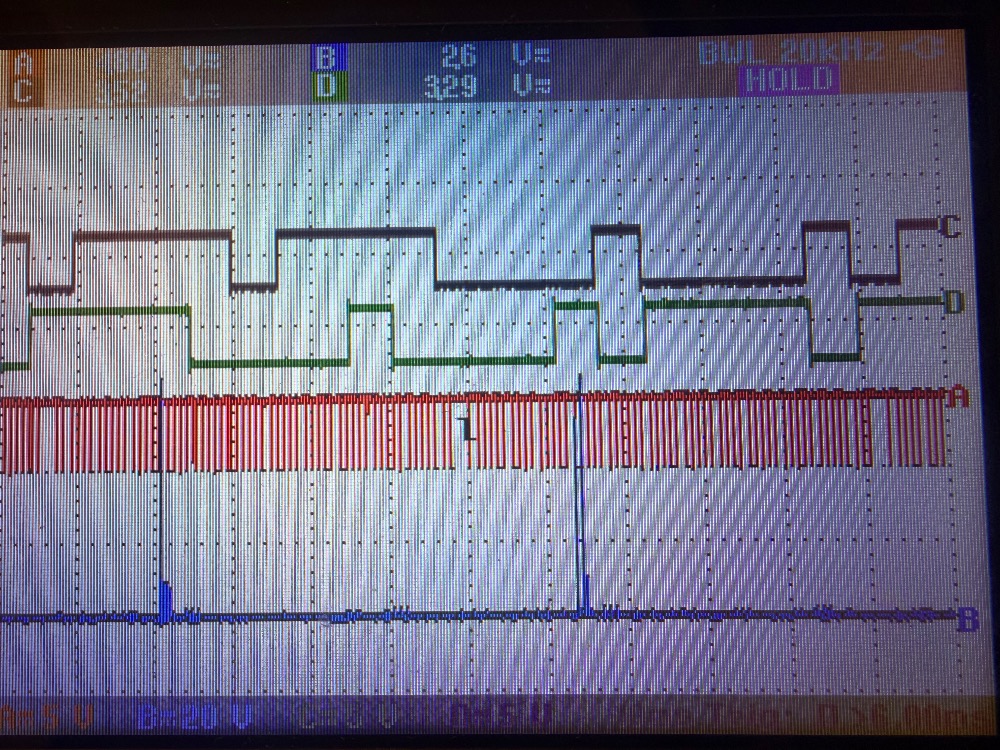
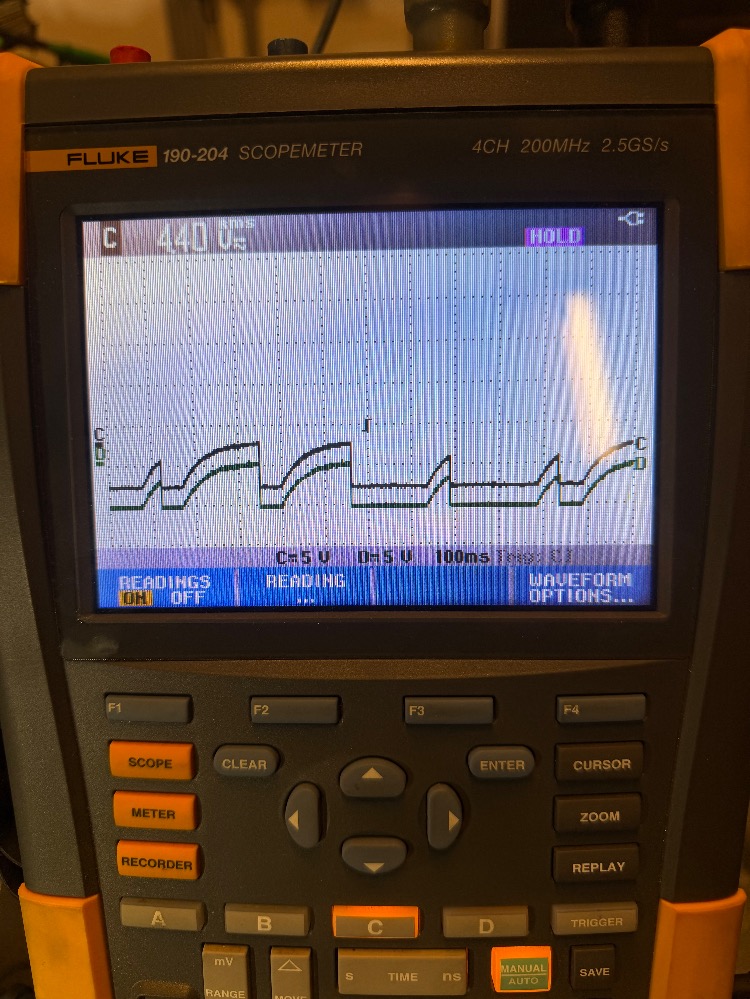
Here I’ve added COP1 on ChC and CMP11 intake cam on ChD.
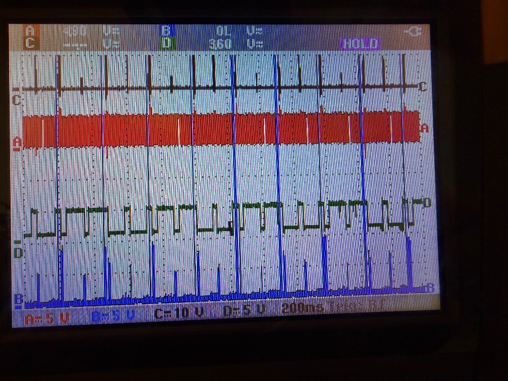
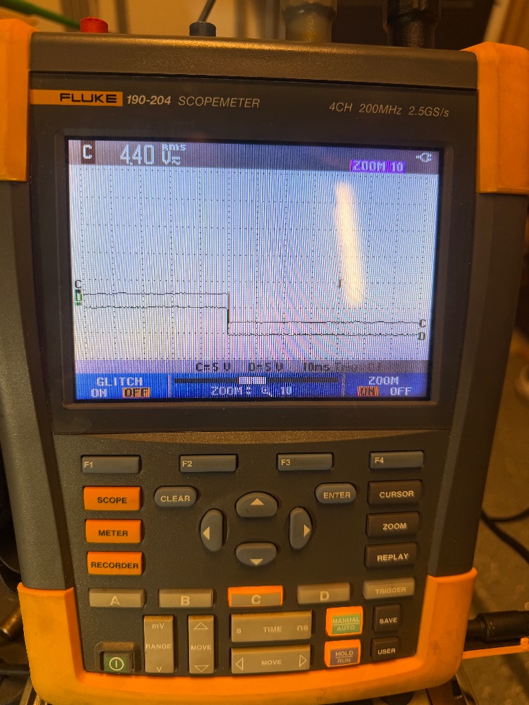
Here it is again at 40ms interval.
Please Log in or Create an account to join the conversation.
- aggiediesel01
-
Topic Author
- Offline
- New Member
-
- Posts: 15
- Thank you received: 4
Here’s the fuel sample (right) I pumped out compared to what I had in my lawnmower can (left)
FORSCAN screen capture of cranking event.
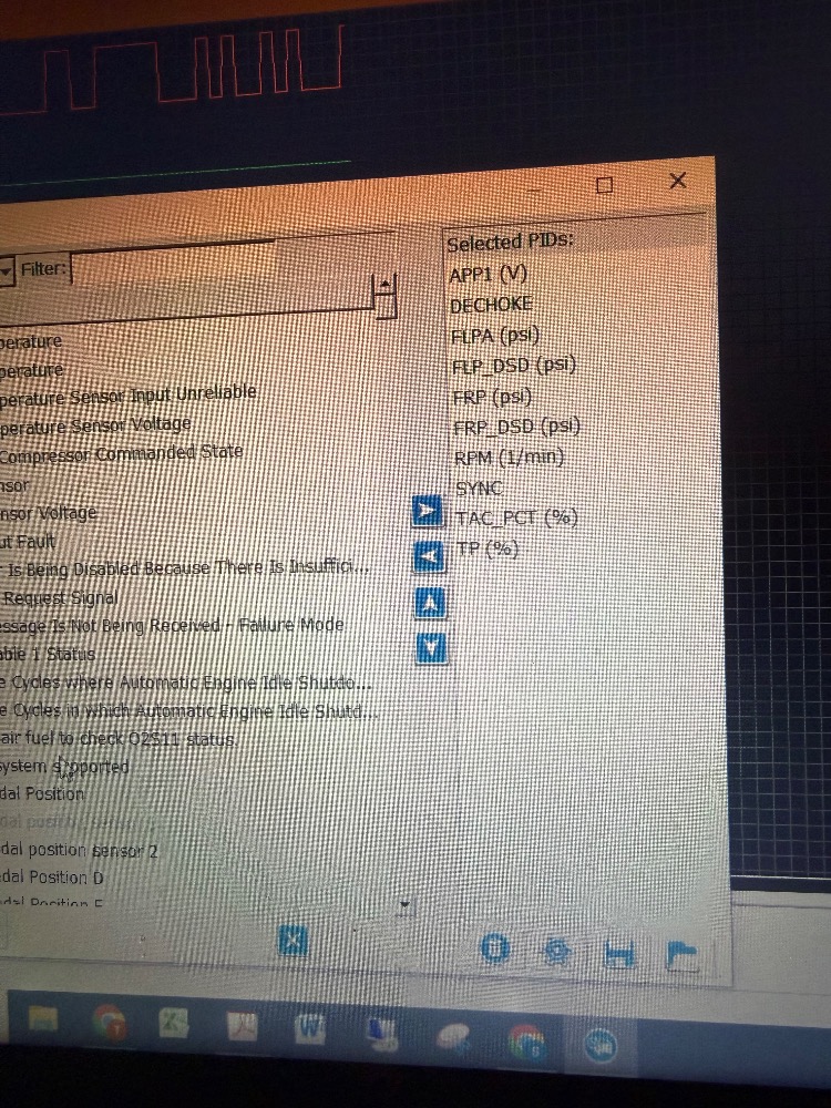
Parameters Monitored in Forscan.
2 cranking events with a throttle blip.

Please Log in or Create an account to join the conversation.
- aggiediesel01
-
Topic Author
- Offline
- New Member
-
- Posts: 15
- Thank you received: 4
Please Log in or Create an account to join the conversation.
- aggiediesel01
-
Topic Author
- Offline
- New Member
-
- Posts: 15
- Thank you received: 4
In my posted waveforms above, can anyone confirm that the timing is correct during a cranking cycle? The signals don't mean much to me because I've never worked with this engine before and the sensors are in odd physical positions related to the rotational position of the crank.
I've read in the manual that the active camshaft control is disabled until the engine is running and temp is up. but I know it needs the CMP signal to start, it just doesn't try to adjust cam timing until the other parameters are met.
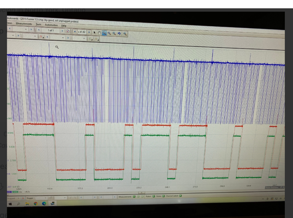
I found the signals from the PCM to the Fuel Pump module (FPM & FPC) are PWMs but it does not match in any noticable way to the 30ms ripple on the fuel injector lines.
FPM
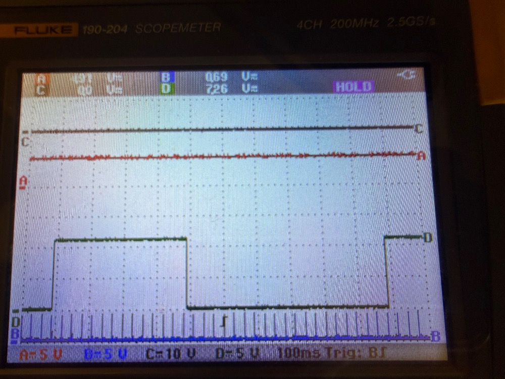
FPC I had to trigger on the PWM to get a good capture.
Please Log in or Create an account to join the conversation.
- aggiediesel01
-
Topic Author
- Offline
- New Member
-
- Posts: 15
- Thank you received: 4
Please Log in or Create an account to join the conversation.
- Noah
-

- Offline
- Moderator
-

- Give code definitions with numbers!
- Posts: 5005
- Thank you received: 1116
Did you discover the source of the oil intrusion into the engine harness? I have seen some GM products push oil and coolant into the harness but haven't run into it yet on one of these.
Was there any engine mechanical work performed on this before or since you have owned it? Not everyone just has the timing tools hanging around, so since you mentioned you used them to verify mechanical timing makes me think maybe you were in here before? Not being accusatory, just trying to put pieces together.
"Ground cannot be checked with a 10mm socket"
Please Log in or Create an account to join the conversation.
- aggiediesel01
-
Topic Author
- Offline
- New Member
-
- Posts: 15
- Thank you received: 4

Please Log in or Create an account to join the conversation.
- aggiediesel01
-
Topic Author
- Offline
- New Member
-
- Posts: 15
- Thank you received: 4
Please Log in or Create an account to join the conversation.
- Noah
-
- Offline
- Moderator
-
- Give code definitions with numbers!
- Posts: 5005
- Thank you received: 1116
When you measured low side fuel pressure with a gauge, was it close to the FLP. Pid? Also, you said "low side pressure bleeds down as expected during cranking". What do you mean by this? I would not expect fuel pressure to bleed down during cranking. Excuse me if I am misinterpreting your statement.
Will the engine fire on alternative fuel?
That was quite a bit of oil in the PCM! This was discovered during the no start diagnosis, correct?
"Ground cannot be checked with a 10mm socket"
Please Log in or Create an account to join the conversation.
- aggiediesel01
-
Topic Author
- Offline
- New Member
-
- Posts: 15
- Thank you received: 4
"This may be a circuit integredy test carried out by the PCM, but as of now I am unsure." - Good point, it will be good to know the answer to this question incase I'm chasing something that's normal, but I haven't previously seen anything in the service manual or the PCED that describes this. I do know that the PCM can perform an injector test via the scan tool but that hasn't been called out by the PPTests yet. The PCM does pass it's self test with no codes.
"Since you are scoping the injectors, are you seeing the computer applying voltage and ground to the injectors during cranking?" - I can see a spike of over 60vdc when cranking but it happens twice in 720deg, not once. If it's supposed to be a PWM, it doesn't last very long. I don't have a good capture of that wave form because I haven't been able to correctly set up the filtering on that channel yet. I've tried a couple things but I've struggled with trigger timing and filtering options here.
"but as I said, I'm not clear where you are connected, or what is the voltage range of your captures." - I have the scope setup as follows:
10:1 ChA: CKP(Pin2 SigRTN, Pin3 CKP) 5v/div,
10:1 ChB: Fuel INJ1 (Pin2 INJ1, Gnd) 20v/div,
10:1 ChC: COP1 (Pin1 COP1A, GND) 2v/div,
10:1 ChD: CMP11 Intake (Pin2 CMP11, Pin1 SIGRTN) 5v/div, also using ChD with regular meter probes 1:1 to look for weird voltages.
In some of my captures I have adjusted the time base to capture more or less and in the later posted captures I've adjusted channel B to 1v/div to zoom in on the 30ms voltage ripple. I did try my best to make sure the scales were included in each capture so they'd be visible to anyone looking but let me know if I can clear anything else up.
"When you measured low side fuel pressure with a gauge, was it close to the FLP. Pid?" - Yes, the requested and measured low side pressure was close to what I measured.
"Also, you said "low side pressure bleeds down as expected during cranking". What do you mean by this? I would not expect fuel pressure to bleed down during cranking. Excuse me if I am misinterpreting your statement." - The bleed down was part of the PPTest A11, the FP is disabled and you crank the engine. The PPT describes that the fuel pressure should fall while cranking the engine. The confusing part for me was the HP side, that pressure didn't seem to drop very much during cranking with the fuse pulled. It would drop a bit and then stop. At the time I didn't check to correlate the stop in the drop of fuel pressure with the "Dechoke" PID going positive but that could have been why, observing the HP side of the fuel system wasn't part of the PPT.
"Will the engine fire on alternative fuel?" - I have tried spraying what I thought was a decent amout of starting fluid into the MAP sensor hole right on top of the manifold and it won't fire. Maybe I didn't spray enough but I definitaly didn't get anything from this. When I look into the map sensor hole, I can see the top of the intercooler so I'm pretty sure there's direct access to the intake ports here and not a subchamber in the intake like with the PVC hose connected nearby.
"That was quite a bit of oil in the PCM! This was discovered during the no start diagnosis, correct?" - Yes, the first time the PPTs ask you to pull the connectors to check for damaged pins on a DI engine is Test DI#5. I was very supprised by that and I thought for sure I'd figured it out but oh well here I am, I'm not giving up yet.
Please Log in or Create an account to join the conversation.
- Noah
-
- Offline
- Moderator
-
- Give code definitions with numbers!
- Posts: 5005
- Thank you received: 1116
For each channel you are saying you are probed into 2 circuits. Ch A is going to have to be on pin 2, or pin 3. I don't understand how you are connecting the scope the way you are describing it.
Every time I have ever used my scope, the ground lead goes to battery negative and each channel probes one circuit. Forgive me for not following you on this point.
"When I look into the map sensor hole, I can see the top of the intercooler "
Spray it in the throttle body. If you remove the map, you should be looking into the intake manifold. The intercooler is in front of the radiator, so I'm not sure where you're looking here.
Is there a scan tool injector balance test that can be tun KOEO?
"Ground cannot be checked with a 10mm socket"
Please Log in or Create an account to join the conversation.
- aggiediesel01
-
Topic Author
- Offline
- New Member
-
- Posts: 15
- Thank you received: 4
As for the map sensor and intercooler, this engine uses an air to water intercooling system so there is a heat exchanger in the intake manifold and one down infront of the radiator with water hoses connecting the two. The airflow path goes through the throttle body and then it drops down low on the intake side of the engine and then up through the intercooler and into the cylinder head.
I haven't found or heard of any function test with the injectors that is availiable while cranking but that doesn't mean much since I'm kind of new to the ecoboost platform.
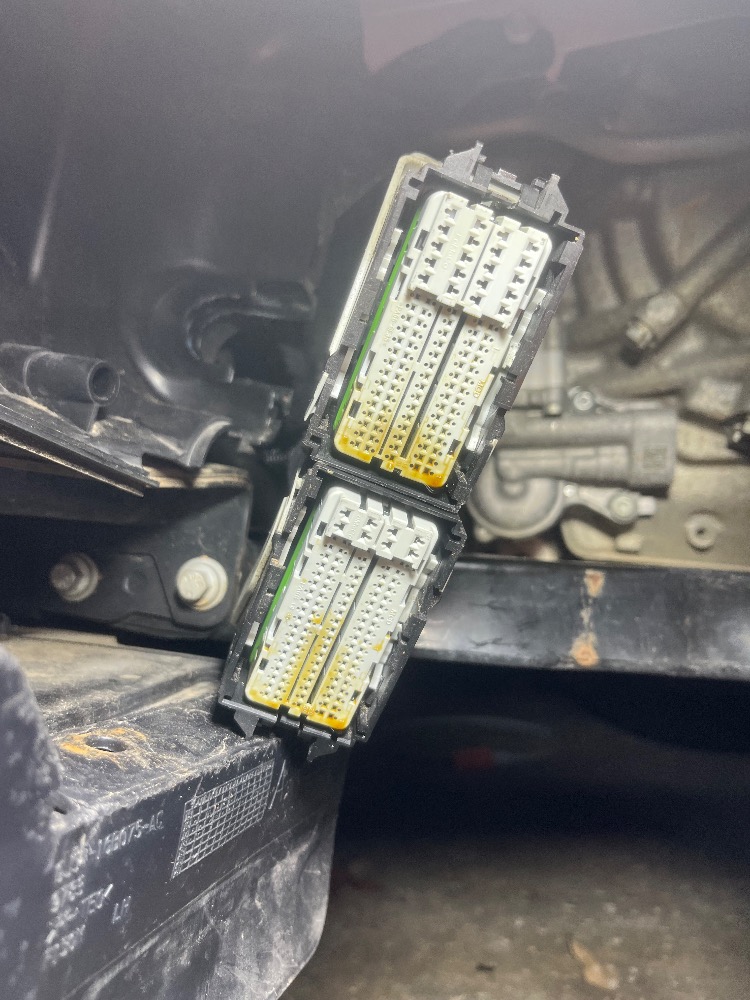
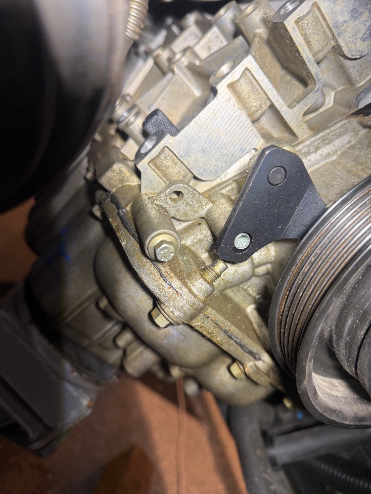
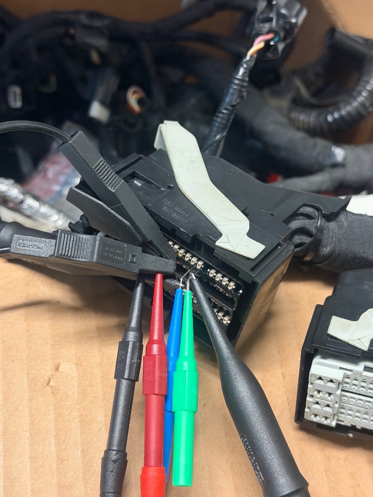
I've highlighted my probe grounds in green in the picture below for INJ1 and COP1.

This one is how I tied into the CKP signals
Please Log in or Create an account to join the conversation.
- aggiediesel01
-
Topic Author
- Offline
- New Member
-
- Posts: 15
- Thank you received: 4
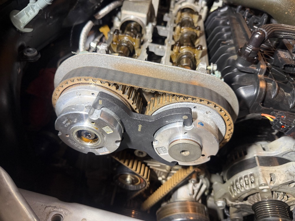
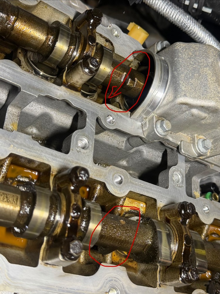
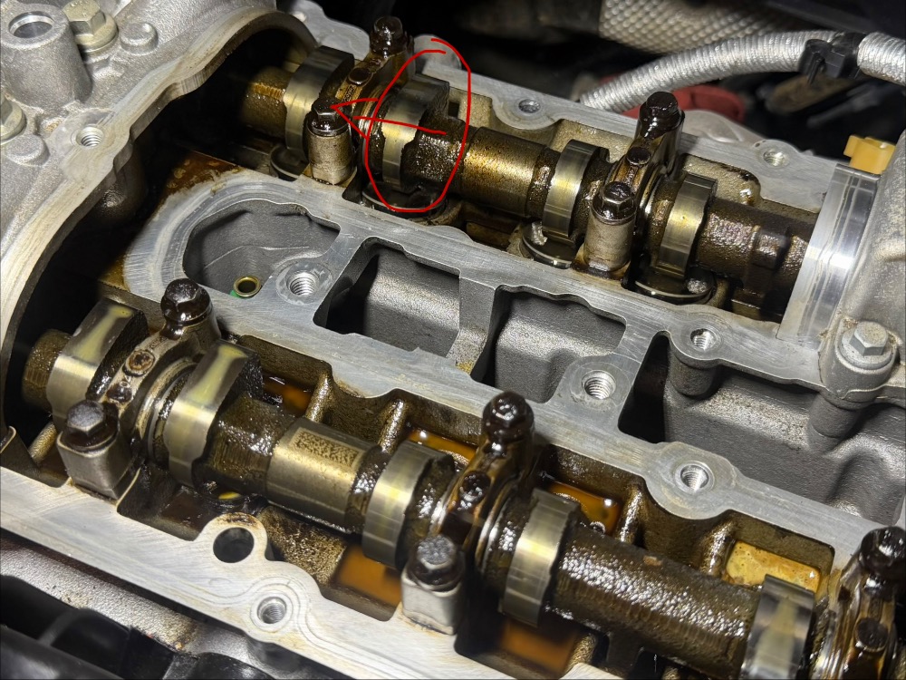
How is that possible if all the timing belt tools fit the cam phasers correctly when the crankshaft is pinned and the CKP alignment tool fit properly too. I wish I had taken pictures when I had all those installed. I was going to but there not in my phone. I’ve got to go borrow the timing tool set tomorrow and set everything up again.
And if those still fit properly, what could have failed? The phaser internally? How does that happen? And how do I have pretty reasonable compression in each cylinder? I think I’ve got a buddy with a borescope, I’ll check if I can borrow that too. I haven’t heard anything that sounds like interference during any of my cranks. This is too weird to make sense right now.
Please Log in or Create an account to join the conversation.
- Noah
-
- Offline
- Moderator
-
- Give code definitions with numbers!
- Posts: 5005
- Thank you received: 1116
[attahment=17199]Screenshot_20251205_074218_Chrome.png[/attachment]
The cam and crank correlation appears to be significantly off compared to this one.
The balancer is not keyed on this engine if I am remembering correctly. So it is possible for the balancer (and the crank sensor reluctor) to become misaligned even if the engine is in proper mechanical time, but your cam sensors never align as the ones in the examples.
At least now you know WHY it's not starting, the question now is what happened?
"Ground cannot be checked with a 10mm socket"
Please Log in or Create an account to join the conversation.
- aggiediesel01
-
Topic Author
- Offline
- New Member
-
- Posts: 15
- Thank you received: 4
Please Log in or Create an account to join the conversation.
- Noah
-
- Offline
- Moderator
-
- Give code definitions with numbers!
- Posts: 5005
- Thank you received: 1116
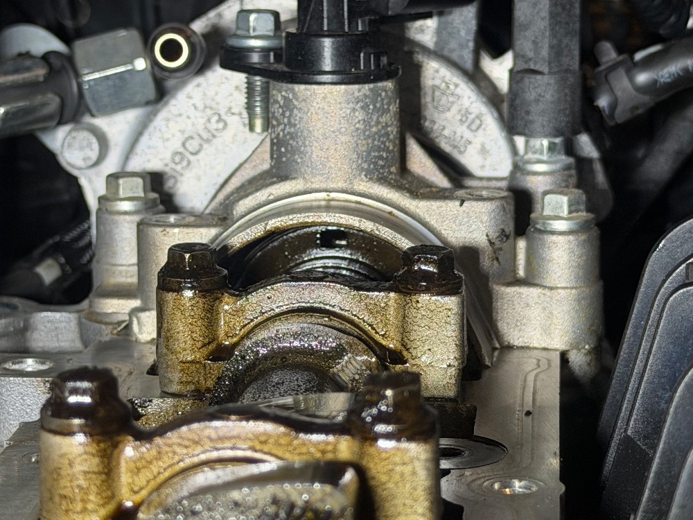
You could see if the camshafts will turn with the gears locked in the tool. That would prove if they are capable of locking up.
I can only imagine your disappointment when the harness and PCM didn't fix it. If I had seen that I probably would have gone the route as you.
I am curious to see what regular good compression is on this engine when you get it back together considering there is no black and white spec that I can seem to find.
At this point, I'm willing to bet that the injector circuits are behaving as designed.
Please keep us posted with your progress!
"Ground cannot be checked with a 10mm socket"
Please Log in or Create an account to join the conversation.
- aggiediesel01
-
Topic Author
- Offline
- New Member
-
- Posts: 15
- Thank you received: 4
Please Log in or Create an account to join the conversation.
- aggiediesel01
-
Topic Author
- Offline
- New Member
-
- Posts: 15
- Thank you received: 4
Please Log in or Create an account to join the conversation.
- aggiediesel01
-
Topic Author
- Offline
- New Member
-
- Posts: 15
- Thank you received: 4
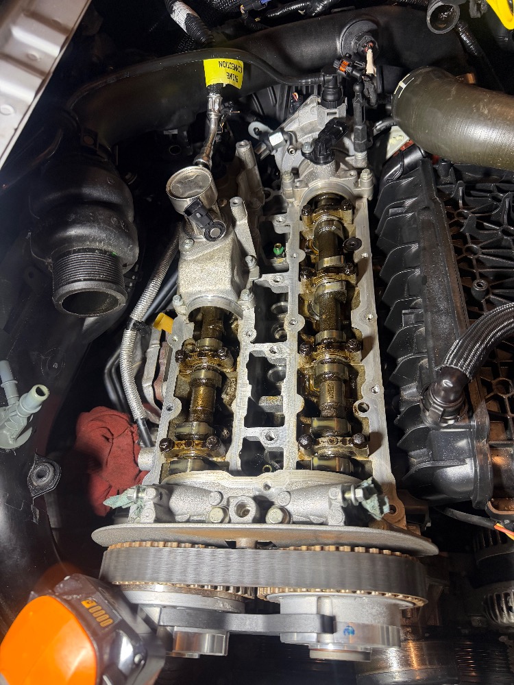
Spinning it by hand gives me enough signal to match them up. I got close with my initial guess but not close enough.
Closer but not yet when I zoomed in

This is much better Ill check it one more time with the starter motor just before I put the valves cover back on.
Please Log in or Create an account to join the conversation.
- Noah
-
- Offline
- Moderator
-
- Give code definitions with numbers!
- Posts: 5005
- Thank you received: 1116
"Ground cannot be checked with a 10mm socket"
Please Log in or Create an account to join the conversation.