Old School 1995 ford f 150 5.8 litre- EEC- Fuel pump and ignition Diagnostics analysis confirmation and labscope setup verification questions
- hobbsautomotiverepair
-
 Topic Author
- Offline
- Junior Member
-

- Posts: 37
- Thank you received: 7
Chris Hobbs
Please Log in or Create an account to join the conversation.
- Noah
-

- Offline
- Moderator
-

- Give code definitions with numbers!
- Posts: 4997
- Thank you received: 1116
Unfortunately, I have no experience with that scope and no real world experience troubleshooting advice regarding the old EEC IV Ford fuel injection system.
The only reason I'm chiming in here at all is because questions about that vintage truck seem to go unanswered or get very few responses and I don't want you think youre being ignored.
Someone may have some experience and advice to aid you on this one, but that system was pretty much dead and gone by the time I started learning diagnostics. For me, it's too old and if someone brought it to the shop, I would likely turn it away. I try my best to keep up with the cars coming through the shop today.
I hope you understand and I hope someone here can help you with what you're looking for!
"Ground cannot be checked with a 10mm socket"
Please Log in or Create an account to join the conversation.
- Tyler
-

- Offline
- Moderator
-
- Full time HACK since 2012
- Posts: 6090
- Thank you received: 1538
www.amazon.com/LAUNCH-Oscilloscope-O2-2-...izador/dp/B0C9D7J996
I haven't used that specific scope, but I wouldn't worry too much about damaging it. I've never known anyone to ruin a lab scope through normal (or abnormal) use.
My goal. i want to see if i'm getting crank signal and id like to match that up on the scope accordingly.
If you're going after the crank signal, I'd probably start at the Ignition Control Module. Charm.li has the OEM diagrams for reference:
charm.li/Ford/1995/F%20150%202WD%20Picku...m/Wiring%20Diagrams/
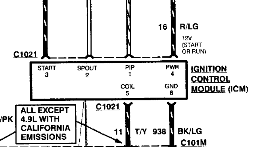
I'd start with two channels. One for the PIP at pin #1 at the ICM, the other for SPOUT at pin #2. Use the included backprobes. Scope ground to the B- post.
You could add a third trace with a secondary ignition pickup on the #1 spark plug wire for reference, if it helps. But, since it's a new tool and a new test, I'd encourage you to keep it simple for now.
My next inquiry is with the fuel pump. with this being a 95 f 150 5.8, i believe the crank signal must be seen by the pcm ignition control module for the spout and fuel pump to stay running? i may be completely wrong on this. but otherwise the regulator drains the unused fuel back to the tanks.
The PCM has to see an engine speed signal in order to close the fuel pump relay, right. But it will also do a key on fuel pump prime, without any engine speed signal. Are you getting a key on pump prime?
Fuel draining back to the tanks wouldn't be related to the PCM, but is purely a mechanical function of a failing regulator or check valve in the fuel pump.
Please Log in or Create an account to join the conversation.
- hobbsautomotiverepair
-
Topic Author
- Offline
- Junior Member
-
- Posts: 37
- Thank you received: 7
Please Log in or Create an account to join the conversation.
- hobbsautomotiverepair
-
Topic Author
- Offline
- Junior Member
-
- Posts: 37
- Thank you received: 7
Please Log in or Create an account to join the conversation.
- Tyler
-
- Offline
- Moderator
-
- Full time HACK since 2012
- Posts: 6090
- Thank you received: 1538
ok so to answer your question yes, i am getting a prime, however it is only about 5-7 psi. surely not enough to fire injectors?
Yeah that's way too low! Charm.li indicates fuel pressure should be 30-45 PSI.
i am getting pulse signal at injectors and i have pulse sigal at coil secondary wire.
Good! The presence of injector pulse would tend to suggest that the PCM is getting the engine speed signal, so you likely don't need to scope PIP and SPOUT.
so i bought it lol but it does say california on the sticker under hood but also says ferderal emissions. think thats confusing me as far as which diagrams to look up on mitchel do you know of how to verify this fact?
I'm not sure how to verify which emissions level it's at. RepairLink, maybe? I did notice that most of the OEM diagrams on Charm.li are annotated to show any differences with Cali emissions.
so in this case i will not need attenuation as there are not high voltage,
Correct. I didn't see a max input voltage in the user manual? But 200-300V is common. You won't be anywhere close to that unless you're testing primary ignition.
in the instructions it discusses grounding the whole scope itself which in and of itself is where all of my second guessing came from. but your saying its ok to simply connect red lead to the wire im testing and just ground the other wire?
Yeah, the manual is a little bit vague about making connections. This is the part you're referring to, right?
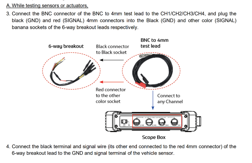
I wouldn't hesitate to go red lead to what you're measuring and black to B-. You can always try it on a known value first, just to get comfortable. A 12V battery, or a 5V sensor for example.
im humbling myself here because i know this sounds silly but sure is different now not having guys in the bay next to you to go to for advise and your the only one in the shop running things:) Appreciate your and everyones knowledge and time.
No worries! Helping each other is why we're here.
Please Log in or Create an account to join the conversation.
- hobbsautomotiverepair
-
Topic Author
- Offline
- Junior Member
-
- Posts: 37
- Thank you received: 7
Please Log in or Create an account to join the conversation.
- hobbsautomotiverepair
-
Topic Author
- Offline
- Junior Member
-
- Posts: 37
- Thank you received: 7
Please Log in or Create an account to join the conversation.