Alternator not charging.
- Vlad1
-
 Topic Author
- Offline
- New Member
-

- Posts: 13
- Thank you received: 0
1.6L engine.
The car showed battery light, CEL and all other instrument cluster lights, I pulled over, turned the engine off and it would not start.
The battery was discharged. I took the car home and recharged the battery.
The battery is able to run high beams light for 30+ mins when fully charged. The voltage after overnight charging is 13.2V, after power load - 12.5V.
Now, when I start the engine, the voltage drops to 11.9V, so the alt is not charging.
Further tests. When the key is in On position - battery light is on, the light turns off after the engine is started.
Ground - checked PPF, all ground connections, some took apart, cleaned and put back together. Just to be sure, bypassed the ground altogether by connecting battery (-) to the engine block with jumper cable. That did not help.
Alternator - installed fully, tightened belt, the pulley is confirmed spinning when the engine is running.
Voltage.
- When Off
- White wire - 12.57V
- White/black - 0V
- White/green - 12.56
- White wire - 12.24V
- White/black - 0.68V
- White/green - 12.25
- When the car is running
- White wire - 12.01V
- White/black - 10.95V
- White/green - 11.99V, then drops to 10.96V
I found this forum after watching this video , but my symptoms are a bit different. I do not have a full power loss in either of the regulator circuits.
Another observation. If the car is running at the fully charged battery that has a battery charger attached to it and supplying 12V/5A, I can see the battery voltage start going up to 14.5V.
Where can I get the wiring diagrams to run the diagnostics as it was shown on the video?
BTW, the car has a non-working power antenna, also some other minor intermittent electric problems.
Thank you
Please Log in or Create an account to join the conversation.
- Desmond6004
-

- Offline
- Platinum Member
-

Getting involved in discussions because I have a lot to learn still.
Please Log in or Create an account to join the conversation.
- Andy.MacFadyen
-

- Offline
- Moderator
-

- Posts: 3357
- Thank you received: 1037

First test is unplug the 3 pin connector on the alternator and check for battery voltage at each of the three terminals in the plug. Both the White-Green and the White should be live with the ignition on ---- if not check the 80a and 30a fusse and for wiring damage or connector corrosion between the plug and the fuses. Next with it still unplugged and ignition on test for near battery voltage on the black-white wire --- I would also do this test with tungsten test light --- which should glow dimly.
If these tests are okay reconnect the plug and put the voltmeter across the battery terminals , back probe the black and white wire at the alternator and supply it with battery voltage through the test light. With the engine running if the alternator is okay it should start charging
" We're trying to plug a hole in the universe, what are you doing ?. "
(Walter Bishop Fringe TV show)
Please Log in or Create an account to join the conversation.
- Tyler
-

- Offline
- Moderator
-
- Full time HACK since 2012
- Posts: 6124
- Thank you received: 1541
At the risk of differing from Andy (who is a sharp cookie), I think you're done.
 You need an alternator. It has everything it needs to do it's job, and still isn't. Your testing shows a working light circuit, a working regulator power circuit, and no opens in the main power or ground to the alternator.
The only part that might suggest an issue is the change in voltage you saw on the white/green wire. A drop of 1V over a Main Relay circuit isn't great, obviously. But the 11V you saw should be enough to run the alternator regulator. It doesn't help that the alternator isn't charging during these readings. :silly: If you still have doubts, you can take a jumper from the white cable to the white/green wire and see if it makes any difference. If it does, we can dig deeper into the Main Relay circuit. If it doesn't, you still need an alternator.
Please Log in or Create an account to join the conversation.
- Andy.MacFadyen
-
- Offline
- Moderator
-
- Posts: 3357
- Thank you received: 1037
") We ain;t differing Tyler ---- foobared alternator
We ain;t differing Tyler ---- foobared alternator  is most likely cause. Not sure if these units are easy to fix some Denso units can have the regulator and brush box changed in about 10 minutes with alternator on still he car
 " We're trying to plug a hole in the universe, what are you doing ?. "
(Walter Bishop Fringe TV show)
Please Log in or Create an account to join the conversation.
- vinnyAudi
-
- Offline
- New Member
-
- Posts: 14
- Thank you received: 2
Sent from my SM-N920V using Tapatalk
Please Log in or Create an account to join the conversation.
- Vlad1
-
Topic Author
- Offline
- New Member
-
- Posts: 13
- Thank you received: 0
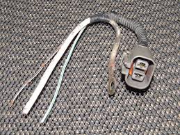
So again, the voltages are taken at the terminal of 2-wire plug, (not the alternator coupling terminals). Also, the voltage on the solid wire was taken while it is attached to the alternator. The plug is disconnected from the alternator and measured, white wire is connected to the alternator while measured.
With key switch off:
- white wire -- 12.67V
- white/black wire -- 0V
- white/green wire -- approximately 12.68V
With key switch on:
- white wire -- 12.34V
- white/black wire -- 11.97V
- white/green wire -- 12.34V
The number in red looks suspicious to me, my understanding it should be around 1V when the engine is not running, but I am not confident if this "around 1V" is obtained from the B/W wire while it is connected or disconnected.
When the plug is connected, I get a bit less than 1V on the B/W wire (key "on", engine off), through the sewing needle with which I tapped the wire.
In a day or two I should get a more solid connectors to tap into those wires. This is it for now...
Please Log in or Create an account to join the conversation.
- Andy.MacFadyen
-
- Offline
- Moderator
-
- Posts: 3357
- Thank you received: 1037
" We're trying to plug a hole in the universe, what are you doing ?. "
(Walter Bishop Fringe TV show)
Please Log in or Create an account to join the conversation.
- Vlad1
-
Topic Author
- Offline
- New Member
-
- Posts: 13
- Thank you received: 0
You might be right though. I'll wait until testing with tungsten wire circuit tester and only then will give up on it.
Please Log in or Create an account to join the conversation.
- BobbyM
-
- Offline
- New Member
-
- Posts: 7
- Thank you received: 3
Take a test light to battery positive and with a t-pin, back-probed on the white black wire, touch that wire with the engine running and see if you hear the alternator kick on.
Please Log in or Create an account to join the conversation.
- Andy.MacFadyen
-
- Offline
- Moderator
-
- Posts: 3357
- Thank you received: 1037
It is a fairly standard 3 wire alternator complete with regulator, if you can find an alternator that will accept the v pulley and fit the mounting brackets it should work.
" We're trying to plug a hole in the universe, what are you doing ?. "
(Walter Bishop Fringe TV show)
Please Log in or Create an account to join the conversation.
- Andy.MacFadyen
-
- Offline
- Moderator
-
- Posts: 3357
- Thank you received: 1037
" We're trying to plug a hole in the universe, what are you doing ?. "
(Walter Bishop Fringe TV show)
Please Log in or Create an account to join the conversation.
- Vlad1
-
Topic Author
- Offline
- New Member
-
- Posts: 13
- Thank you received: 0
There was something else that helped (I was not able to monitor the alternator sounds since I had to go inside the car to start it so I'm not sure if this really is an alternator waking up. ut if not, then I have no explanation for what I am writing below).
If the battery is fully charged (overnight on 5A current) and shows 13.2 volts,
and also, if I put 30A input on the battery charger and keep it connected to the battery while the car is running,
then the alternator seems to wake up and the voltage goes up to ~14.1-14.5V depends on revs (and this means yes, the voltage starts responding to the engine revs).
If I unplug the charger, nothing changes immediately, but in around 3-5 mins the voltage goes down to 12.2-12.3V range and and does not elevate in response to engine revs.
Please Log in or Create an account to join the conversation.
- Vlad1
-
Topic Author
- Offline
- New Member
-
- Posts: 13
- Thank you received: 0
Andy.MacFadyen wrote: The brush pack and rectifier looks like an easy fit
ebay link to rectifer and brush pack assembly
Hey Andy,
Thank you for the answer. So, this is what this alt needs, right?
I've never done alternator overhaul. Do you think it's going to be like an easy swap?
Please Log in or Create an account to join the conversation.
- Vlad1
-
Topic Author
- Offline
- New Member
-
- Posts: 13
- Thank you received: 0
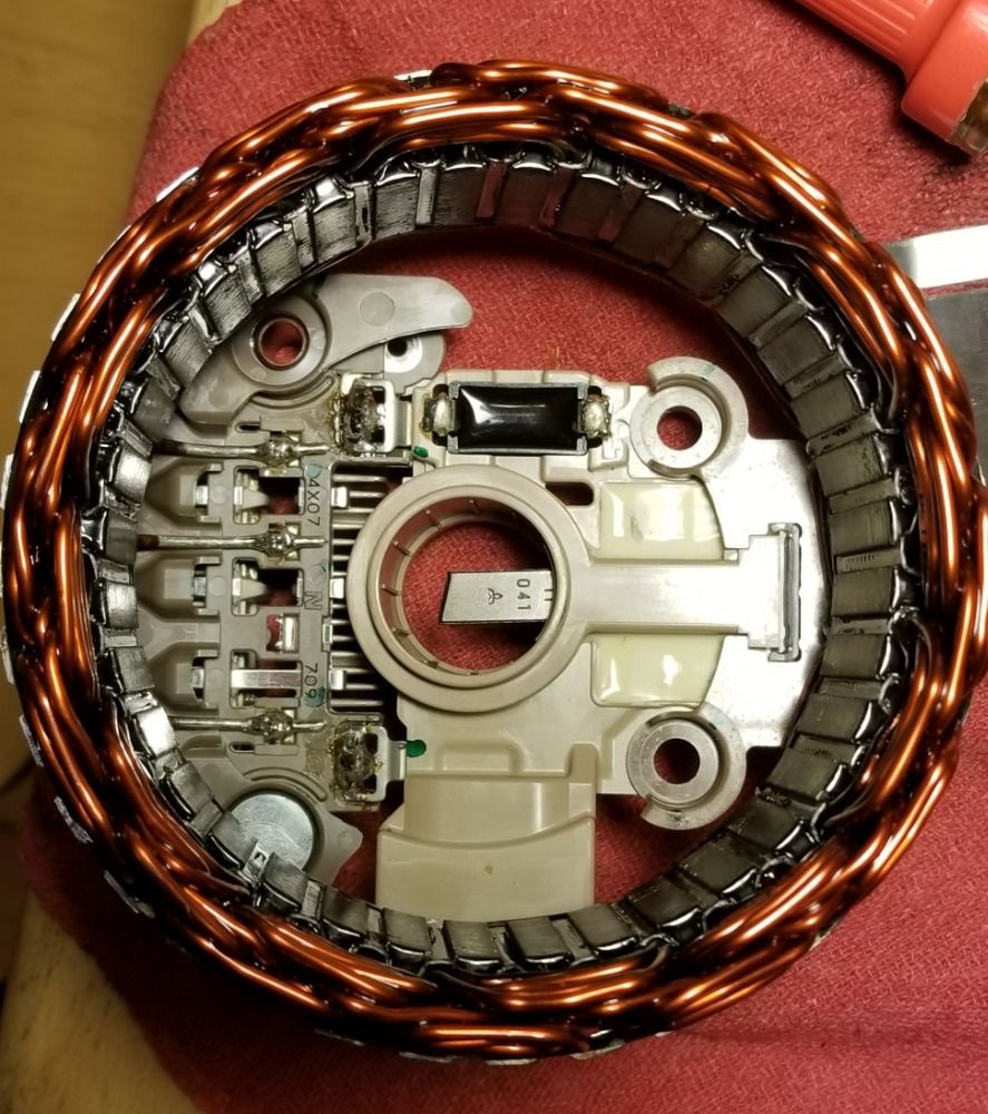
What would be the way to test the voage regulator and/or diodes? I want to understand what failed in my alternator and that I'm placing the working replacement.
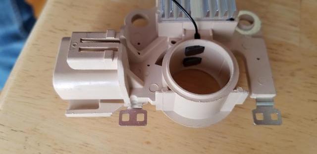
These are the pictures of the stator and electronics inside and new part that came in.
Please Log in or Create an account to join the conversation.
- juergen.scholl
-

- Offline
- Platinum Member
-
- Active partschanger
- Posts: 1233
- Thank you received: 462
Any diode that allows current to flow in both or no direction is at fault and you will have to replace the rectifier as a unit.
Concerning the regulator there is no practical way I know of to "test" it easily on the bench, iout of the car.If the brushes and the spring tension/collector slip rings are fine then you just may want to put a new one in...
With the rest of the alternator confirmed healthy you can check the regulator IN the car by applying varies voltage levels to the control wire. The alternators output should respond if it is sound.
An expert is someone who knows each time more on each time less, until he finally knows absolutely everything about absolutely nothing.
Please Log in or Create an account to join the conversation.
- Vlad1
-
Topic Author
- Offline
- New Member
-
- Posts: 13
- Thank you received: 0
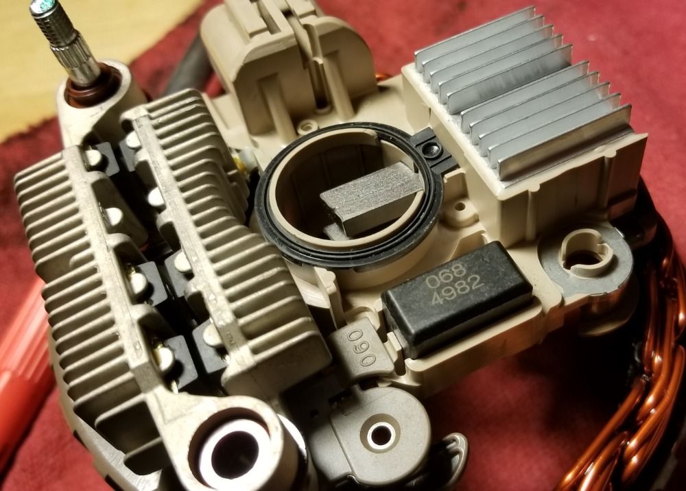
However, I think I found something that looks like potential culprit.
On the new regulator, there's continuity of the top most brush to the metal contact seen on the low left side, see the picture below.
In the non-working alternator, the same path shows no conductivity.
Which way is it suppose to be?
I am hesitating because 5he original voltage regulator looks more advanced than the replacement one (check the pictures in the previous post).
And there are other soldering spots which purpose I cannot understand or guess.
Should this circuit be conducting, like on the replacement part or is it going live when I supply the regulating current?
Please Log in or Create an account to join the conversation.
- Vlad1
-
Topic Author
- Offline
- New Member
-
- Posts: 13
- Thank you received: 0
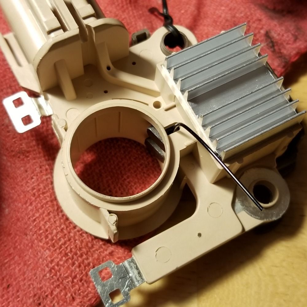
Put everything together with a new voltage regulator.
Applied 9V to the lower regulator contact (lower if looking as the alternator is installed on the car) and cranked the pulley to read the voltage on the B-post (negative attachment being the body in both of the cases).
Initially it was giving jumps from 0V to 2-2.5v which should be normal I guess.
Then after a minute or two me playing with it it started to show the battery voltage and stopped responding to the cranking.
I disassembled and re-assembled again. No changes.
The voltage does not go up between the B post and body no matter if I try to apply 3V or 9V.
I'll try to put it on the car and check on the car tomorrow. But having doubts it will work.
Not sure what killed that initially proper response...
Please Log in or Create an account to join the conversation.
- Vlad1
-
Topic Author
- Offline
- New Member
-
- Posts: 13
- Thank you received: 0
Ordered a Denso unit. ETA is like 3 weeks.
Please Log in or Create an account to join the conversation.
- Vlad1
-
Topic Author
- Offline
- New Member
-
- Posts: 13
- Thank you received: 0
It looks like it is equally likely that I keep getting defective parts or units as well as I get undamaged units/parts, but destroy them by improper testing technique or some sort of undiagnosed failure at car's electrical system.
One thing I know for sure - the ground path is checked by several more or less reliable ways and should be sufficient. The resistance of the car body measures around 0.03 -0.05 Ohms.
Is there any way to diagnose the supplied voltage to the pigtail connector while the alternator is off car? Any particular sense to measure the voltage on B/W and B/G wires of the pigtail connector while the alternator is not installed?
What would be theoretical way to damage the alternator by testing it?
Can I damage the regulator by supplying 9V from the battery to the green/white connector while NOT supplying the 12V to the B post and just reading the voltage from that post while cranking the pulley? Must I supply the voltage on the b/w wire terminal as well to make sure I don't damage the electronics?
Please Log in or Create an account to join the conversation.