Chevrolet Captiva 2008 2.0 diesel throttle body wide open
- mjmeodmt
-
 Topic Author
- Offline
- New Member
-

- Posts: 15
- Thank you received: 26
I do board level repairs on pretty much any PCB for the last 10 years+ specializing on laptop motherboards. I got into auto electrics a year or so ago, doing mostly repairs on circuit boards for car modules(ecu,pcm,bcm and others) Following a lot of Danner's videos I started getting interested in diagnosing cars.
Engine: z20s1 | 2.0 diesel
Year: 2008
Attached an Wiring Diagram ( www.autocats.ws/manual/chevrolet/tis0409...va/start_captiva.htm )
History before I got involved:
- Engine has been over-all'd twice. (redone)
- Loom has been taken out & checked=OK
- Car has had a lot of jump starts
- and possible unknowns...
State:
The car starts after a few attempts, you have to pump or hold down the accl_pedal. Once its going, idle is rough and on higher rpm it lets out a lot of black smoke.
Then I got involved:
Note: battery & ignition was either off or disconnected when certain actions were taken place, like unplugging the ECU
I received the ETC(Electronic Throttle Control) body whole. The mechanic stated that it stays wide open and it seemed to keep wanting to go more open as if the motor inside didn't get any sense of the position it is at. I thought okay TPS faulty...
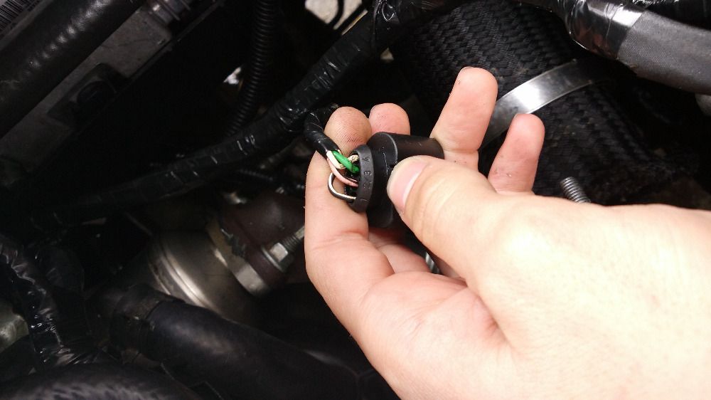
This ETC is all in one. 4 Pin connector. (see; Throttle Plate Actuator @ bottom image)
1. Ground
2. B+ 12V
3. Control
4. Feedback
I hooked up my bench PSU and see if I can replicate the issue. And sure I did. Giving it GND, 12V and 5V control pulse 25Khz(I tried 400hz freq didn't respond) 50% duty Cycle; made the motor open the butterfly and wanting to keep opening it past the stop position. (Which is actually part of the case, the gear inside is physically stopped) So again here I thought maybe the TPS is acting up or something. So I opened the module I reworked the PCB and checked the TPS which in this case is hall effect 3 pin. It responded fine when you move the gear like the butterfly would operate normally. (From a low voltage to near 5V). But no feedback.
After the rework/reflow and various testing, I hooked up the bench PSU and the Generated PWM and it actually worked. It responded perfectly. Feedback was also good on the scope. So I gave it back to the mechanic and they tried it.... Only to call me back and say its still doing the same. Sad face...
I went out to the garage and took my scope with along with my pwm generator. I hooked it up and tested the throttle actuator disconnected from the engine and it once again worked fine. I the proceeded to check the control wire on the car since I was there. Only to find 3.5V and no pulse (Ignition ON) & same when engine running.
I found the 3.5V on the Control pin for the Throttle Plate Actuator very odd. I checked the TMAP, Fuel Rail pressure sensor they gave 5V...
So that was weird... Here I found out it has been jump started a lot and it stood for a long period as well. Using the diagram I figured maybe its just a bad wire from the ECU to the plug of the ETC. Here I also found out they checked continuity when they removed the loom.
We then unplugged ECU as it it in engine area. We found some wetness inside the plugs but it seemed more like an oil based liquid. I plugged it back in after cleaning the liquidness and letting the plug dry / air used as well. I rechecked continuity quick and saw it was good.
Once everything was back in I checked pin 3 (control) again on the ETC plug I found 4.4V for a short period and then back to 3.5V. I though uhm I wonder if the ECU got wet. So unplugged everything got it out and on the bench
Once opened I inspected it and it was actually pretty good inside, no sign of anything bad... I proceeded to check the pin to & from the ETC. And found that its one of the Bosch driver chips. I then traced and checked what else runs off that driver chip, I found that the Boost pressure actuator also get's its control from that Bosch Driver. Went back to the car plugged the ECU back in and checked the voltage on the Boost Pressure Actuator and found the same 3.5V which now make me think that maybe that drive chip is faulty. I haven't touched anything else yet because I need to know how the ETC works in this car especially the Control Signals from the ECU
So after the long essay my question. Is the 3.5V normal or suspect? Because I don't have enough experience with this chev to say that its either normal or not. Does anyone here know how its driven? Because I only worked from what I could research on the net regarding these ETC's and how they are controlled and all the info I got worked on 5V PWM.
I typed this out will update because I want to trace the Fuel Pressure and Tmap pins and see where they go inside the ECU. If they come from the same Bosch driver then I don't know what the hell, maybe its half broken then. But if they go to another Driver (which i think they may because they are just sensors and not actuators) it could mean that the driver chip needs replacing... The other thing is that it could be a faulty part that works on the same circuit that's drawing a lot of current on the control pin possibly.
Anyways thanks and sorry for the long essay. I figured i'd give you all the info, to get an idea of my process in short

while alive { live(toFullest=true) }
Please Log in or Create an account to join the conversation.
- mjmeodmt
-
Topic Author
- Offline
- New Member
-
- Posts: 15
- Thank you received: 26
The datasheet explained fault detection on Short To Ground & Open Load on the channels to give 3.5V which is exactly what we are getting.
So no work done on the ECU closed up for now (will reseal later). I figure we should go through the actuators and components running off the same driver(TLE6244).
EDIT: I completely forgot to mention the DTC's.... Will pull them again tomorrow. There was something about the ETC, Crank sens, and something else. But I'll get clear info on that tomorrow. Because sometimes it wouldn't even throw codes. Random...
while alive { live(toFullest=true) }
Please Log in or Create an account to join the conversation.
- Tyler
-

- Offline
- Moderator
-

- Full time HACK since 2012
- Posts: 6127
- Thank you received: 1542
BUT, I'm super happy to follow along - this TLE6244 document you linked is AWESOME. :woohoo: Read the whole thing, and some parts several times because I don't speak designer-ese. All kinds of details in there about how this chip talks to the rest of the computer, circuit fault detection, fault coding. This kind of technical information really helps to put SD material in perspective.
The datasheet explained fault detection on Short To Ground & Open Load on the channels to give 3.5V which is exactly what we are getting.
The open load diagram, for reference:
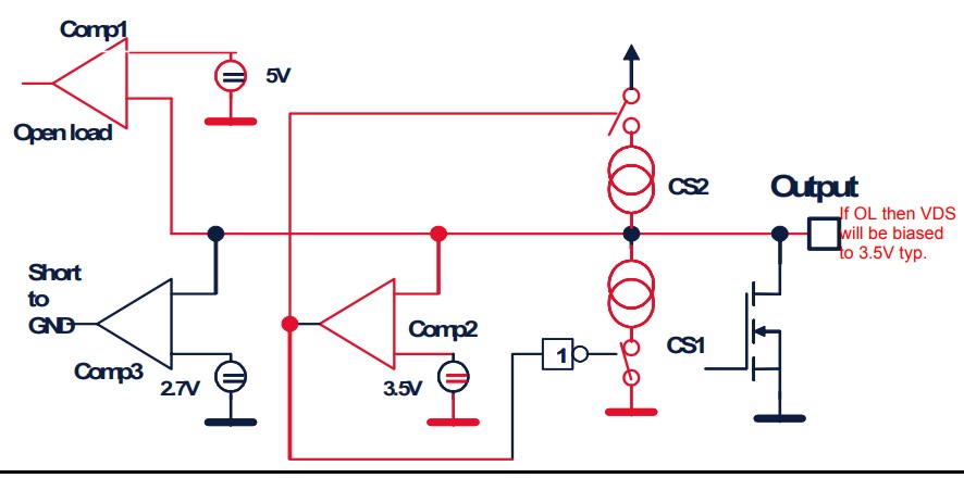
Check my understanding here? With the channel off, Comparator1 sees less than 5V, so the drain gets biased at 3.5V. That'd infer that the normal voltage on this circuit is higher than 5V, right? Mostly I'm trying to figure out if the 3.5V is a reaction to a perceived open load. If this is a low side driver, then shouldn't there be voltage coming from the throttle to the TLE6244?
Also, back to the Captiva. I don't know this engine, but most of the diesels I'm familiar with have throttles like this for either EGR functionality or runaway control. I'm not sure that a stuck open throttle alone would cause black smoke?
Please Log in or Create an account to join the conversation.
- Desmond6004
-

- Offline
- Platinum Member
-

IF this is like the Captivas we get in New Zealand this part caught my attention. We had a Captiva with starting issues last year that ended up goingmjmeodmt wrote: We then unplugged ECU as it it in engine area. We found some wetness inside the plugs but it seemed more like an oil based liquid
to the dealers for ECU coding - but they found that the vehicle had gone through a pool of water and the engine bay fuse box had taken a dip and was full of corrosion. It was easier for them because they had another vehicle right next to it and they started swapping parts ( the fuse box has a lot of pins to test with a meter, sometimes changing parts is more economical than testing)
Getting involved in discussions because I have a lot to learn still.
Please Log in or Create an account to join the conversation.
- mjmeodmt
-
Topic Author
- Offline
- New Member
-
- Posts: 15
- Thank you received: 26
@Tyler : That's awesome glad you enjoyed it, here is a better one with way more detail regarding that chip it also has a little image near the top. You should have seen this chip by now if you opened ECU's before. Bosch like them. Altho the Bosch ones are usually just a number like 30xxx this one is from Infineon. Feel free to ask more about these chip level stuff. It's what I do. I do have some Bosch me7.1/7.5 Schematics of the whole ECU PCB. It's old but it will give you a really good idea on how they work.
Check my understanding here? With the channel off, Comparator1 sees less than 5V, so the drain gets biased at 3.5V. That'd infer that the normal voltage on this circuit is higher than 5V, right? Mostly I'm trying to figure out if the 3.5V is a reaction to a perceived open load. If this is a low side driver, then shouldn't there be voltage coming from the throttle to the TLE6244?
To answer your question regarding your understand on the OPEN LOAD Detection. I don't know
(Direct Parallel Control of 16 channels for PWM Applications)
As far as I understand it there should be a signal going to the Throttle Actuator on pin 3. and nothing from it. They have a FEEDBACK pin that gives feedback. When I tested this Actuator on the bench I supplied GND, 12V, 5V @ 25Khz 50% duty cycle PWM, and on the feedback I got between 0.6V and 1.3V depending on the butterfly position. So when you close it the voltage goes down and opening takes it up. (Or the other way around, I can't remember too many things to keep in mind
 )
)When I opened the Throttle Actuator/Body. They have a PIC18F inside doing the controlling of the Stepper Motor and the TPS signal. They step the voltage down from 12V to 5V inside as well. They have a H-bridge setup inside to drive the motor. Which again tells me that the Control signal is merely just a signal... But the thickness of the control wire makes me wonder a bit. (See Image attached)
So as far as the Throttle Body/ETC/Actuator goes I think it's fine. Even with it disconnected we still get 3.5V on the control line. But yeah open load could mean unplugged... Confusion overload pretty much.
I'm going to do some more tracing later will report here what I find. But I think the Injectors maybe running of the same chip or at least they are controlled via it I think... Will report back later.
Agreed.Sounds like the throttle is a symptom instead of the cause. I'm thinking you're going to find more output issues.
@Desmond6004 Uhmm interesting. It's not really a starting issue, I mean it starts and runs but its a struggle and its not running very smooth nor efficiently. But since it stood for some time I think I'll inspect the fuse box and report back.
Thanks for the input guys, really appreciated !
while alive { live(toFullest=true) }
Please Log in or Create an account to join the conversation.
- mjmeodmt
-
Topic Author
- Offline
- New Member
-
- Posts: 15
- Thank you received: 26
See Image Attached.
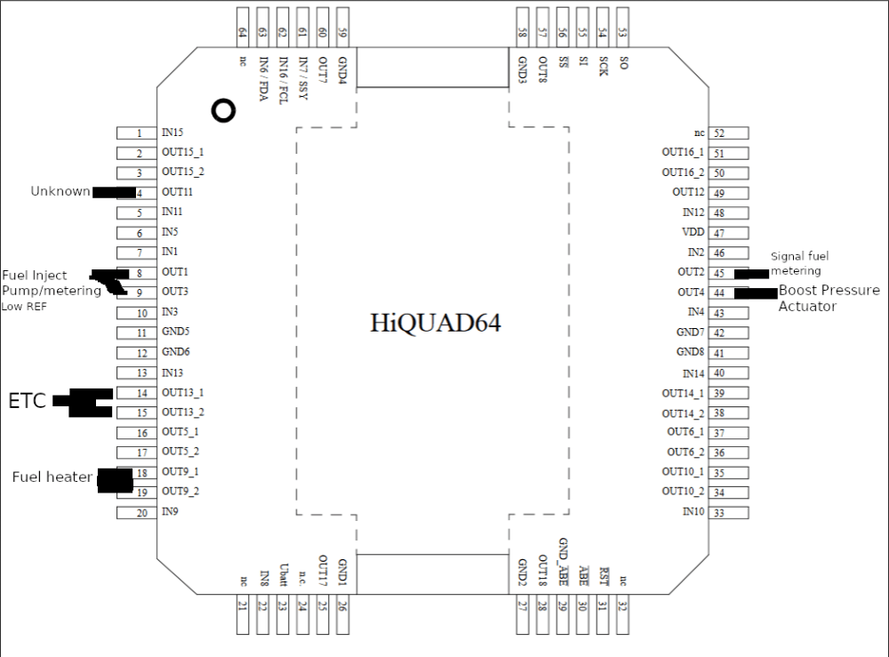
PINS ON THE LEFT IS ECU CONNECTOR PINS ON THE RIGHT ARE CHIP PIN OUT.
ETC Pin 59(J2) = Pins 14&15 OUT13_1 & _2
Boost Pressure Actuator Pin 15(J2) = Pin 44 OUT4
Pin 91 Unknown = Pin 4 OUT11
Fuel Injection Pump (metering unit) Pin 49(J2) = Pins 8 & 9 OUT1_3 Both Seems to be for the LOW REF. (Physically connected on PCB)
Fuel Heater Relay Pin 68(J1) = Pins 18 & 19 LOW SIDE SWITCHED
UPDATED:
Cooling Fan Relay(LOW SIDE) Pin 90(J1) = Pins 38&39 OUT14_1&2
Aux Fan(LOW SIDE) Pin 69(J1) = Pins 34&35 OUT10_1_2
AC COMP LOW SIDE Pin 29(J1) = Pins 36&37 OUT6_1_2
Will Try and edit this if I find more.
AND HERE ARE THE CODES.
P0100
P0110
P0402
P0401
P0403
P0340
P0335
P0095
P0190
P02E0
While I was there I had the ECU plugged in and open. I checked the Circuit. The Pin for the ETC Control seems like its a 12V PWM it goes up to near 12V when the ignition is turned on and then goes down to 0V then after a short time it goes to 3.5V. (The near 12V is when its opening and then stop. When the ignition is turned on it does that no idea if that is normal?)
Nothing gets hot the CPU and Power supply chip gets warm as expected.
PSU part on the PCB:
12V input OK
GND input OK
5V Supply OK
3.3V Supply OK
I don't think its the ECU in this case. It kinda seems to respond and do what its supposed to do. Unless there is some IC that's acting up.
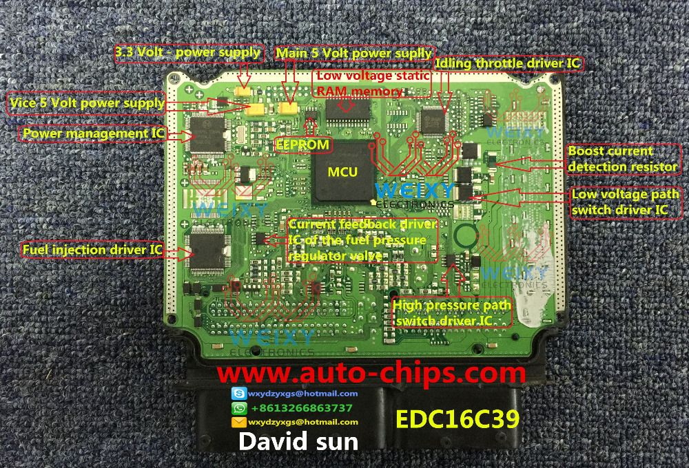
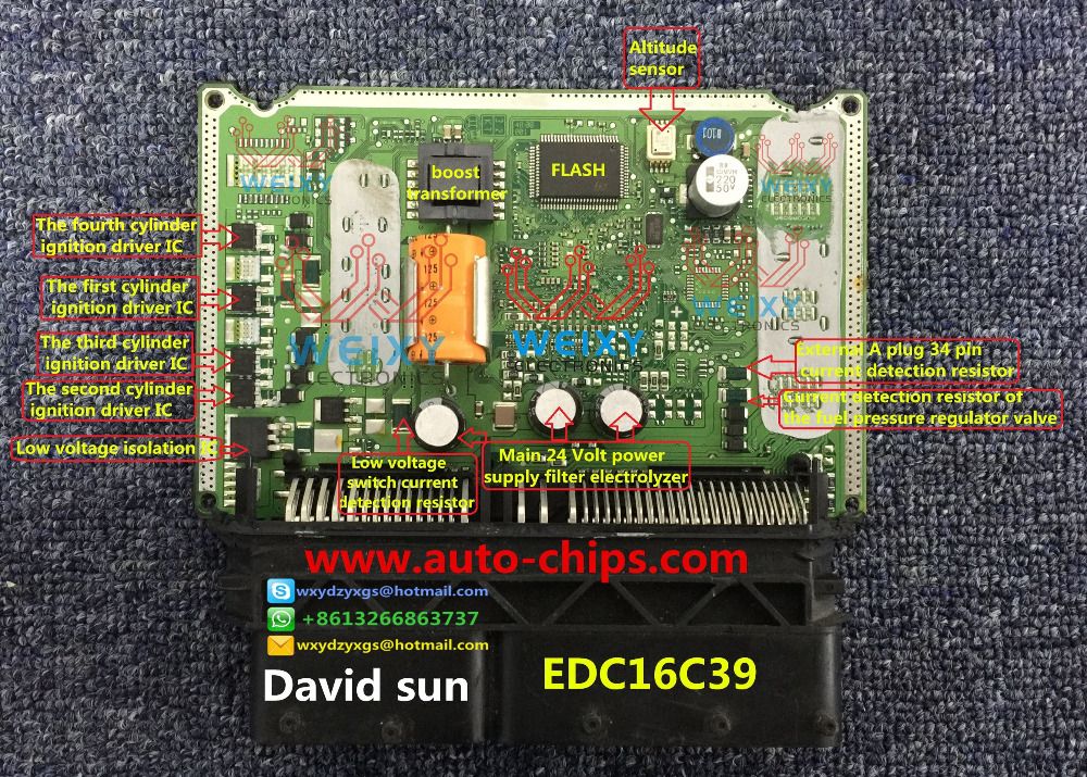
While I had the ECU I did rework the IC pins. for both the TLE6244x and what seems to be some other controller. (I found this EDC16C39image
And they marked most of the IC's I don't agree about the TLE on that page because who ever did that labeled it as the Fuel Injection Driver (alone?) which I found to not be the case. Unless that is a bit of an either older or newer model/version PCB(ECU)...
Anyways the car starts a little easier now, but I can't say that its a definite "change" Idle is still rough and it would stall after a few seconds to maybe a minute of idling. Uhm sometimes while trying to start it would knock insanely hard(well knocking is the only thing I can compare it to, I'm no pro with Diesels, I know they are roughish)
Will report back with more info when I get some...
while alive { live(toFullest=true) }
Please Log in or Create an account to join the conversation.
- Tyler
-
- Offline
- Moderator
-
- Full time HACK since 2012
- Posts: 6127
- Thank you received: 1542
mjmeodmt wrote: @Tyler : That's awesome glad you enjoyed it, here is a better one with way more detail regarding that chip it also has a little image near the top. You should have seen this chip by now if you opened ECU's before. Bosch like them. Altho the Bosch ones are usually just a number like 30xxx this one is from Infineon. Feel free to ask more about these chip level stuff. It's what I do. I do have some Bosch me7.1/7.5 Schematics of the whole ECU PCB. It's old but it will give you a really good idea on how they work.
I've only ever opened up a ECM once. :blush: Mostly because our rebuilder swore up and down that all was well, yet still had a dead driver. I traced it to a smoked chip on the board, but didn't have the expertise to repair it. Plus, there's no way my shop could warranty it. :lol:
Anyway, I'd appreciate any of the chip level info you think would be valuable.
Also, I did a quick search on Digikey - that TLE6244 chip isn't made anymore? :silly:
Please Log in or Create an account to join the conversation.
- Andy.MacFadyen
-

- Offline
- Moderator
-
- Posts: 3357
- Thank you received: 1037
I would also want to check glow plug operation -- they run at key on prior to start up and for 8 to 20 seconds after start up --- normally this can be spotted by the the battery voltage unlike a gasoline engine because the glow plugs draw a lot of amps the battery voltage will linger down about 12v or even slightly less until the glow plugs are shut down by the ECU and charging voltage quickly returns to normal 14.2 to 14.6v
" We're trying to plug a hole in the universe, what are you doing ?. "
(Walter Bishop Fringe TV show)
Please Log in or Create an account to join the conversation.
- mjmeodmt
-
Topic Author
- Offline
- New Member
-
- Posts: 15
- Thank you received: 26
Hard to start common rail diesel that runs rough and smokey after start up ---- has anybody done an injector leak-back test ? also a check the low side fuel pressure pump(s) output.
I would also want to check glow plug operation -- they run at key on prior to start up and for 8 to 20 seconds after start up --- normally this can be spotted by the the battery voltage unlike a gasoline engine because the glow plugs draw a lot of amps the battery voltage will linger down about 12v or even slightly less until the glow plugs are shut down by the ECU and charging voltage quickly returns to normal 14.2 to 14.6v
Not that I know of. I will make sure that they check that. Thank you for the input.
I still need to get up to speed with all the "extra" bits. Coming from a purely computer/electrical side I still need to learn a ton of stuff. At least I get the basic mechanical idea of how things work but that's about it.
@Tyler :
I've only ever opened up a ECM once. :blush: Mostly because our rebuilder swore up and down that all was well, yet still had a dead driver. I traced it to a smoked chip on the board, but didn't have the expertise to repair it.
Ahh haha okay. That's all good at least you took the step and it turned out to be worth it. Repairing or replacing damaged chips on PCB boards aren't that complex. Simple hot air or rework station and some good liquid flux (some paste could work but I dislike it), steady hand with tweezers. And of course the correct heat. From my experience so far most ECU PCB's are less dense than laptop board for instance. So something like 150-250 degrees Celsius should do the trick to remove and resolder chips.
There is a guy on youtube that have some videos doing chip repairs and I'm happy with his way of doing it. (Not that I have some Auth over all chip repairs, haha... I'm just saying that I have seen some people do it and it was baaaad) This guy used to do the same repairs like I do. Board level repairs on Laptops/Desktops and so on... LINK HERE
Yes that is a major point! Apart from "warranty" on the repair, I have more issue with the Responsibility you know the; What if.... Not what if it breaks again... What if something happens and someone gets hurt. That's why I don't mess with ABS of Airbag systems or any other obvious safety devices. I'd merely use the repaired ECU as a good way of ensuring the fault if that's the case. Because these ECU's are so damn expensive so you can't just willy nilly replace them. But you do get those people that would most likely insist on using the repaired ECU, haven't had a case like that yet but I would probably let them sign a legal document about taking the risk or something. I dono it gets really complex.Plus, there's no way my shop could warranty it. :lol:
Anyway, I'd appreciate any of the chip level info you think would be valuable.
This discussion has really changed how I look at OEM's. For whatever reason, I always assumed (insert brand here) made all their own components? But they source components from other companies (duh), and do all the work putting them together so it'll work in (insert year/make/model here).
Sure I think I have given you something to look at, at least for the actual replacing of components. Apart from that I think knowing the chips that do the work helps. At least these with documents available that way you can strengthen the diagnostic results when checking voltages and waveforms. Esp with issue we have with the 3.5V now knowing its a possible "open load".
Other than that I'll try and think of things or I'll start a thread somewhere where it fits and I'll share info regarding all this. But questions are welcome that way I know exactly what you or who ever would like to know. Keep in mind I'm no Electronic Engineer...
And yes they all use the same shit. I have found similar chips on other boards as well... It's shocking. And the most common components are Bosch funded/made/designed stuff.
Right I can see that, remember most of the ECU's we work on nowadays were made many moons back. I know those chips are available from 3rd party companies/and online shops like Aliexpress and so on... But urg its hard to find a good source that sell good components.that TLE6244 chip isn't made anymore?
Some interesting links to Bosch Systems and Infineon, most contain datasheets with good info just for some researching and good reads.
Bosch Engine Management System
Infineon Engine Management Details
Like this from Infineon They are pretty much upgrades from the older components...
The ME7.1 & 7.5 ECU its fairly common and the images and docs are freely available online.
autodtc.net/docu/ME71.ZIP
autodtc.net/docu/ME75.ZIP
Those contain pdf's schematics, excel spreadsheets about pin data and some images that point out the chip over functions. Very Very good info, it gives you a really good idea of how the things are setup, like the flow of the board.
Something I learned on laptops are the importance of 3.3V and 5V if you don't have those you don't have anything. Most chips use 3.3V for their basic functions and some other components step that even more down. Ofc those voltages are stepped down from the adapter/battery voltage being 15V-20V and 10V-14V depending on make/type. SO with that in mind checking the integrity of the ECU power supply you should get those at the "power supply section"... Just some info, I'll attached 2 images found online that do some good point out's to give you a idea.
Anyways Looong essay again
while alive { live(toFullest=true) }
Please Log in or Create an account to join the conversation.
- Tyler
-
- Offline
- Moderator
-
- Full time HACK since 2012
- Posts: 6127
- Thank you received: 1542
I have questions! First, when it comes to ECU repair where the case seals together, what's the preferred method to reseal it? Talking about cases that don't bolt together, and rely solely on sealant. Reheat the existing sealant?
Second is about the component level repairs you do on PC's and laptops. The automotive industry has gone far away from repairs like that - replacing starters instead of rebuilding them, new alternators, reman engines and such. Parts are cheaper, less liability, better warranties. Would you say the repairs you do are the norm, or the exception?
Please Log in or Create an account to join the conversation.
- mjmeodmt
-
Topic Author
- Offline
- New Member
-
- Posts: 15
- Thank you received: 26
Glad to share!Yeah the Management IC's are pretty sweet, very interesting stuff. Tons of good info to add to the "Diagnostic Process" esp when it comes to "times" where the ECU/ECM/PCM.... are questioned in regards to possibly being faulty.
I have some answers !
1. Well when it comes to sealant; I found that silicone for "cars" like LINK works... Depending on the location of the "Device" Id use something within that spec, heat/mold/bla bla... and before applying the new sealant obviously remove the old.First, when it comes to ECU repair where the case seals together, what's the preferred method to reseal it? Talking about cases that don't bolt together, and rely solely on sealant. Reheat the existing sealant?
2. The norm... Here in South Africa parts can be really expensive, well everything is pretty much expensive... The thing is sometimes its just not possible to either replace/or/try another part. Because of cost firstly and then sometimes availability and the risk of being taken for a ride...Second is about the component level repairs you do on PC's and laptops. The automotive industry has gone far away from repairs like that - replacing starters instead of rebuilding them, new alternators, reman engines and such. Parts are cheaper, less liability, better warranties. Would you say the repairs you do are the norm, or the exception?
while alive { live(toFullest=true) }
Please Log in or Create an account to join the conversation.
- Tyler
-
- Offline
- Moderator
-
- Full time HACK since 2012
- Posts: 6127
- Thank you received: 1542
mjmeodmt wrote: Yeah the Management IC's are pretty sweet, very interesting stuff. Tons of good info to add to the "Diagnostic Process" esp when it comes to "times" where the ECU/ECM/PCM.... are questioned in regards to possibly being faulty.
Agreed. Definitely helps me to understand what's going on 'behind the curtain' when doing diagnostics.
Well when it comes to sealant; I found that silicone for "cars" like LINK works... Depending on the location of the "Device" Id use something within that spec, heat/mold/bla bla... and before applying the new sealant obviously remove the old.
That's convenient! I have some of that rolling around in my tool cart. :woohoo:
The norm... Here in South Africa parts can be really expensive, well everything is pretty much expensive... The thing is sometimes its just not possible to either replace/or/try another part. Because of cost firstly and then sometimes availability and the risk of being taken for a ride...
Gotcha. Do you find that auto technicians in your area do less 'parts changing' as a result? Or are they just as bad as Americans? :silly:
Please Log in or Create an account to join the conversation.
- mjmeodmt
-
Topic Author
- Offline
- New Member
-
- Posts: 15
- Thank you received: 26
Just as bad... Obvious things do get replaced when they are at fault or even un-repairable or purely just not worth a repair... but in most cases auto techs are the parts changer types... and you end up paying for all those parts even though most of them didn't fix the issue... They just lack electronic knowledge and most will kick against training. It's like electronics are some kinda black magic or something. Alien tech
#EDIT: To add to that question&answer... There is a "gap" here for these types of repairs as well, I mean towards the repairs I do. No one here really does it same goes for Laptops. Low level circuit repairs are very rare, esp people that know what they are doing. So it would be nice to aid in this "parts changer" dilemma with some viable alternative. I'm not greedy when it comes to putting a price tag on whatever repair. I aim for fairness. If its a 5$ repair its 5$, if its quick and painless I don't charge. If its assumed to be a 500$ repair but it actually only cost 20$ I charge 20$. I used to work at a place that run off bullshitting people, taking advantage and so on... And I'm just over that. Id rather not have to explain one day in Heaven you know...
Indeed yeah I love this stuff, keeps my mind busy. Have you ever read/researched (re)mapping Ecus? That stuff is gold too. Getting to know how the software works helps a ton with understanding the hardware side "response" and getting a idea of how the computer uses the info it receives, like how it would think/respond. This Book is a good start and freely available VAGSuite , the guy(book) explains everything really well gives you a whole lot to think about. And VAGSuite gives you example binaries to look at. They have videos on youtube as well.Agreed. Definitely helps me to understand what's going on 'behind the curtain' when doing diagnostics.
But (re)mapping is a whole other ball game... Not something to just play around with!
Anyways all interesting stuff... But I want to get my diagnostic skill up first like SD. Considering buying the ebook for myself as a gift for xmas
while alive { live(toFullest=true) }
Please Log in or Create an account to join the conversation.