2005 Chrysler Town & Country 3.8 P0406 EGR sensor high
- Mechanic 350
-
 Topic Author
- Offline
- Elite Member
-

- Posts: 313
- Thank you received: 15
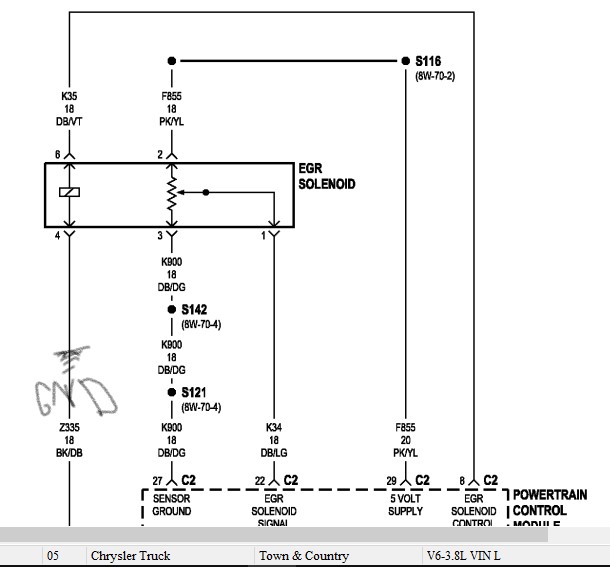
The pin out for this connector according to mitchell diy, is as follows:
1. Dark blue/Light Green= EGR SOLENOID SIGNAL
2. Pink/Yellow = 5V Reference
3. Dark Blue/Dark Green = sensor ground
4. Black/Dark Blue = ground
5. empty
6. EGR Control = Dark Blue/Violet
Now, I'm trying to determine if this circuit is ground or power side switched. I haven't been able to determine that yet. I don't want to
fry the transistor. But what's killing me is that there are two wires going to the computer, which the wiring diagram identifies as egr solenoid
signal on both of these wires. dark blue/violet and dark blue/Light green. I know the 5v ref wire but haven't been able to properly identify
these two wires.
Now, when I checked voltage on those two wires, I coundn't get 12 volts and only got like 3.94 volts on both of those wires. so i don't know
what's going on there. The only wire that does not go to the computer is the dark blue/dark green wire that seemed to power other sensor in
the circuit. I know because of what paul taught me in his book that a solenoid needs a power and a ground. I have followed that. but i have
determined that 3 wires go to the computer. So that's my situation Paul with this car. It keeps coming up.
Please Log in or Create an account to join the conversation.
- Mechanic 350
-
Topic Author
- Offline
- Elite Member
-
- Posts: 313
- Thank you received: 15
Please Log in or Create an account to join the conversation.
- Paul P.
-

- Offline
- Platinum Member
-

- Posts: 457
- Thank you received: 195
What is the voltage on the signal wire KOEO with the sensor unplugged? It should be near 5volts.
If the valve is closed, and your getting 3.97v plugged in, that is not good, it should be under a volt.
Try setting a circuit low code by jumpering the signal wire to sensor ground, KOEO unplugged.
Does a new code set? If so, the signal integrity is good.
You can check the operation of the solenoid by performing a bypass test, you will manually open the valve while the engine is idling ( the engine should respond by rough idle to a stall condition)
Tpin the DB/VT (Solenoid control wire), Test lamp to BAT POS, tap tpin to open the valve, the engine should respond to rough idle or stall), if you monitor the Solenoid signal wire DB/LG at the same time, you should see a voltage change.
If the motor runs rough or stalls, no voltage change on signal, the potentiometer in the valve is bad.
Voltage drop the PWRS and grounds. before replacing the egr valve.
Never stop Learning.
Please Log in or Create an account to join the conversation.
- Desmond6004
-

- Offline
- Platinum Member
-
Getting involved in discussions because I have a lot to learn still.
Please Log in or Create an account to join the conversation.
- Tyler
-

- Offline
- Moderator
-

- Full time HACK since 2012
- Posts: 6124
- Thank you received: 1541
")
Please Log in or Create an account to join the conversation.
- Tyler
-
- Offline
- Moderator
-
- Full time HACK since 2012
- Posts: 6124
- Thank you received: 1541
From memory, 3.9V sounds right-ish to me. Does the code reset immediately? If not, you might have more luck flexing the connector or tapping on the top of the valve itself to make it reset the code. I'd also do as Weycraze suggested - disconnect the sensor and verify 5V on the signal, then short the signal to ground and generate a new code. If you can do that, it's time for a new valve.
Some known good data to compare to. This T+C got a new EGR valve:
www.scanshare.io/share/MBfD4D4Lg02v910poyTTgA
If you buy a new valve, go OE. Aftermarket is trash garbage. VERY easy to install a problem with a part store valve.
Please Log in or Create an account to join the conversation.
- Mechanic 350
-
Topic Author
- Offline
- Elite Member
-
- Posts: 313
- Thank you received: 15
2. I set a code just like you suggested and it did. signal intergrity is good.
3. I performed the bypass test as you suggested. while the engine was idling, I T-pinned the dark blue/violet wire and the engine did NOT stumble or hesitate. The only change I saw was that voltage was pulled down as I touched the wire. I saw a voltage change with this wire.
4. Voltage change was seen on the signal wire; 0.17 volts. engine running. plugged in.
5. I replaced this egr valve in June 2018.
6. The wire going to the computer according to your diagram is DB/VT, my control wire.
7. So the wire that's not going to the computer is my ground wire correct? So that would make my circuit ground side switched?
8. Thank you so much for your help. What's your next suggestion? thanks
Please Log in or Create an account to join the conversation.
- Mechanic 350
-
Topic Author
- Offline
- Elite Member
-
- Posts: 313
- Thank you received: 15
Please Log in or Create an account to join the conversation.
- Mechanic 350
-
Topic Author
- Offline
- Elite Member
-
- Posts: 313
- Thank you received: 15
Please Log in or Create an account to join the conversation.
- Tyler
-
- Offline
- Moderator
-
- Full time HACK since 2012
- Posts: 6124
- Thank you received: 1541
MOROSO321 wrote: sorry tyler, I don't know how to merge the two threads. Can you show me? thank you.
Ah don't worry about it.
") Merging threads is only some a mod can do, anyway.
Merging threads is only some a mod can do, anyway.By the way, you are way to advance for me with those waveforms you sent me. lol. I'm just beginning to understand how to read these waveforms. But thanks. I now have something I can compare to in the future.
Sorry about that! I didn't mean to throw up too much data, just wanted to show the normal potentiometer operation. :blush:
5. I replaced this egr valve in June 2018.
:lol: Yep, been there! I once went through three brand new BWD/Carquest/Zone valves on an Equinox before I wised up and got a dealer part.

Please Log in or Create an account to join the conversation.
- Paul P.
-
- Offline
- Platinum Member
-
- Posts: 457
- Thank you received: 195
performed the bypass test as you suggested. while the engine was idling, I T-pinned the dark blue/violet wire and the engine did NOT stumble or hesitate. The only change I saw was that voltage was pulled down as I touched the wire. I saw a voltage change with this wire.
The Engine should have stalled at this point if the valve did open. Sometimes a fused jumper wire is necessary to perform this as an incandescent test lamp might not provide enough current. If you power up that solenoid and the engine doesnt stumble the valve is not opening.
So the wire that's not going to the computer is my ground wire correct? So that would make my circuit ground side switched?
NO, the Ground for the solenoid is CONSTANT, This is PCM Power-Side Switched. Thats why we went to Bat POS to activate the solenoid. The PCM provides power to energize it, so we'll BE the PCM and energize it with a test lamp or fused jumper wire. You can also use your multimeter in AMPS mode to activate the solenoid.( Most are fused at 10 Amps)
SO, on the Signal Wire DB/DG you have 4.94v unplugged and plugged in you have 0.17 Volts?
This suggests, provided the valve is Closed because its not running rough, that the potentiometer is low volts with the valve closed and high volts with the valve open, or the potentiometer is pooched like Tyler suggests. I'd have to agree with Tyler on that one. You performed a circuit integrity test so the PCM can recognize circuit high/circuit low.
My next move would be to try and energize the solenoid with a fused jumper, to try and open that valve and get the engine to stumble. No response, you need a new valve.
Also, is there voltage present on the on the control wire KOEO plugged in? If there is, check the voltage level on the ground(BK/DB), the voltage levels should be very near the same.
Never stop Learning.
Please Log in or Create an account to join the conversation.
- Mechanic 350
-
Topic Author
- Offline
- Elite Member
-
- Posts: 313
- Thank you received: 15
that my PCM is power side switched? this is killing me. According to page 4 on chapter 3, output solenoids, it says that the solenoid needs a power and a ground.
The wire that goes to the computer is DB/VT, is my control wire. Then ground. But
there's two grounds. sensor ground and I guess the other is chassis ground? Help me to understand. thanks
Please Log in or Create an account to join the conversation.
- Paul P.
-
- Offline
- Platinum Member
-
- Posts: 457
- Thank you received: 195
For the solenoid, always follow the wire that DOES NOT go to the PCM, to determine what's in the PCM.
In this case the, BK/DB Pin 4, goes to chassis GND, therefore the DB/VT(Pin 6) that goes to the PCM(Pin8,C2) has to be the Power Feed.
When the PCM decides it wants to energize the solenoid it applies voltage on the DB/VT wire. This makes it Power Side Switched.
When the transistor at the PCM is turned ON, 12 volts will flow to the solenoid. Thus, this solenoid has a Power feed and a ground.
I think the confusion might be in the labeling of the diagram.
The diagram is labelled EGR SOLENOID. However, the only solenoid is where the DB/VT enters on pin 6 and leaves on Pin 4 BK/DB GND.
The other three wires are for the position of the valve, so the PCM can determine how much it is open.
They show both circuits together and label it as "EGR SOLENOID", not egr solenoid and postion sensor.
SO, the DB/VT is the CONTROL wire, but this control wire provides B+ to the solenoid.
I hope this clarifies this, and the Book is absolutely correct!
Never stop Learning.
Please Log in or Create an account to join the conversation.
- Mechanic 350
-
Topic Author
- Offline
- Elite Member
-
- Posts: 313
- Thank you received: 15
Please Log in or Create an account to join the conversation.