Transmission Electeical
- Jrogers0229
-
 Topic Author
- Offline
- New Member
-

- Posts: 6
- Thank you received: 1
I have had 2 pcm installed. Pick up coil, cap, rotor, alternator,battery.
The voltage regulator went out of the pcm on a trip. Left me stranded for a few days till we finally figured the bad pcm issue. New pcm installed but still didnt make it home. Had another pcm installed along with the above parts.
About a month later alternator gauge went to 0 and check gauge light came on. I thought the pcm was going out again since that's what it did before. Did not get the 0601 code but I do have several other codes. I will get into those. I did wire in an external regulator and it seems to work. The volt meter doesn't work and the check gauge light and check engine light stays on.
The problem I have run across is the 2 wires that went to the plug on the alternator. One is white/blue stripe and the other is dark green/blk. The white/ blue stripe looks to supply 12v to the trans relay and no matter how I wire it the trans will not shift. I think it's in limp mode. I have not checked 5v reference on the trans plug I just got a diagram for that today will check tomorrow.
I do have the following codes.
1594 voltage too high
0622 field control circuit
0743 tcc solenoid
0753 electrical solenoid A
0713 tranny temp(got on start up today)
1763 Gov pressure too high
1765 12v supply relay
1495 evap solenoid.
I have changed every solenoid in tranny and the wire harness.
The evap solenoid has been changed as well.
Been trying to figure this out for weeks any help would be great.
Please Log in or Create an account to join the conversation.
- Paul P.
-

- Offline
- Platinum Member
-

- Posts: 457
- Thank you received: 195

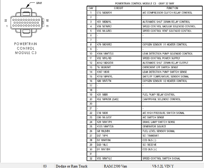
Here is you Alternator Wiring Diagram.
The White wire with the Dark Blue Trace goes to pin 25 of the ECM Connector 3 (Gray)
The other wire the Dark Green goes to Pin 10 of the ECM Connector 2 (White)
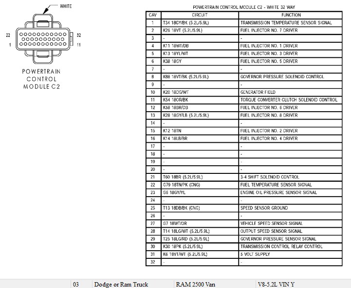
Neither of these two wires go to the tranny.
If you need more info let me know
Never stop Learning.
Please Log in or Create an account to join the conversation.
- Jrogers0229
-
Topic Author
- Offline
- New Member
-
- Posts: 6
- Thank you received: 1

Please Log in or Create an account to join the conversation.
- Paul P.
-
- Offline
- Platinum Member
-
- Posts: 457
- Thank you received: 195
www.bbbind.com/free-tsb/
The wire in question according to my info goes to Pin 25,PCM Gray Connector 3.
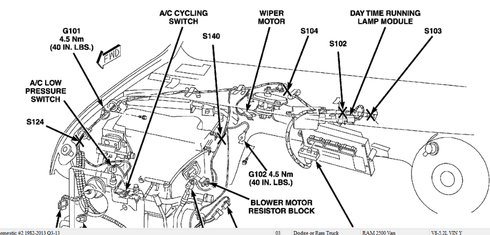
AND, YOU ARE CORRECT, it does provide control power to the trans relay it splits off at Splice 104 which is located...
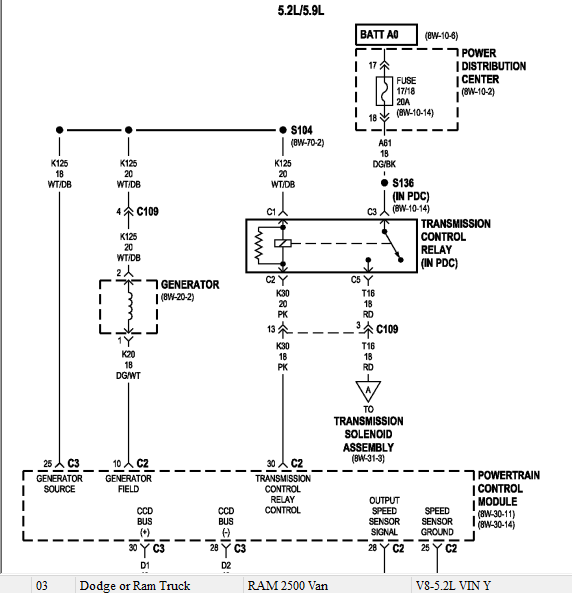
Wow thats poor on chryslers part not to show that on the Generator diagram, but they did label the splice and reference the other diagram
Never stop Learning.
Please Log in or Create an account to join the conversation.
- Noah
-

- Offline
- Moderator
-

- Posts: 5028
- Thank you received: 1119
Thanks for coming though with those diagrams
")
Please Log in or Create an account to join the conversation.
- Jrogers0229
-
Topic Author
- Offline
- New Member
-
- Posts: 6
- Thank you received: 1
Please Log in or Create an account to join the conversation.
- Jrogers0229
-
Topic Author
- Offline
- New Member
-
- Posts: 6
- Thank you received: 1
Still cannot get 12v from whit/ blu stripe wire from back of alternator. Should I have 12v coming from that wire? Stumped for sure.
Please Log in or Create an account to join the conversation.
- Paul P.
-
- Offline
- Platinum Member
-
- Posts: 457
- Thank you received: 195
Never stop Learning.
Please Log in or Create an account to join the conversation.
- Jrogers0229
-
Topic Author
- Offline
- New Member
-
- Posts: 6
- Thank you received: 1
I see that is the wire I am confused about. Does that wire have power on it after the relay or does the relay require that wire to have power on it to work and then the pcm will see the 12v? Does the alternator need to see power on that wire to turn on and off? Today I was testing and I could not get any output out of the alternator, like it wasnt working. Just had everything tested last weekend. I think both the trans and the charging issue are connected just cant seem to solve it. Thx for the replies.
Please Log in or Create an account to join the conversation.
- Paul P.
-
- Offline
- Platinum Member
-
- Posts: 457
- Thank you received: 195
Does that wire have power on it after the relay or does the relay require that wire to have power on it to work and then the pcm will see the 12v?
That wire has 12v on it to the relay. The relay does require power on it to work. The PCM provides the ground path( the pink wire) to energize the relay. This is the 'Control' side of the relay.
Does the alternator need to see power on that wire to turn on and off?
Yes, it needs 12v from the PCM pin 25 connector 3. The PCM will use the other wire the Dark Green/White trace to 'energize' the alternator.
I think both the trans and the charging issue are connected
They most definitely are connected.
The transmission relay might be misleading you depending on how your doing your voltage checks.With the key on youll see 12 v at the relay for the WH/DB wire, but you may or may not see 12 volts on the pink, depending whether the PCM has provided a path to ground.
Never stop Learning.
Please Log in or Create an account to join the conversation.
- Jrogers0229
-
Topic Author
- Offline
- New Member
-
- Posts: 6
- Thank you received: 1
I had to jump the pink wire coming from pin B 31.
The trans relay was not energizing. I was so focused on the white/ blue wire.
I had to put the white/blue wire into my wiring for the external regulator to excite the alternator.
What would make the pcm go out again? It's only a few months old.
Everything is working, maybe not the correct way but gets me started. Thanks to everybody that helped.
Please Log in or Create an account to join the conversation.