Help us help you. By posting the year, make, model and engine near the beginning of your help request, followed by the symptoms (no start, high idle, misfire etc.) Along with any prevalent Diagnostic Trouble Codes, aka DTCs, other forum members will be able to help you get to a solution more quickly and easily!
ECU Running Boost at idle and oscillating boost at 2500 rpm
- SailorBob
-
 Topic Author
- Offline
- Elite Member
-

7 years 6 months ago #23802
by SailorBob
ECU Running Boost at idle and oscillating boost at 2500 rpm was created by SailorBob
I've got a 2008 Kia Carnival ( Sedona in the USA I think ) 2.9L J3 Turbo Diesel which is having some strange turbo issues and I'm trying to understand how the two solenoids which control the turbo actuator normally work.
Just some background for context, the engine was rebuilt a few years ago, and there is what seems to be a long standing combustion leak past the injector threads on one cylinder ( the whole injector well is filled with hard carbon build-up ). The car came to me because the owner started hearing a whining noise a few days ago that he said changed with engine speed. I found that the turbo was active at idle ( 16 g/s & 100 kPa MAP ) and that holding at 2500 rpm the turbo actuator was slowly pumping up and down creating a MAP oscillation of between 98 - 130 kPa.
So, there are two solenoids:
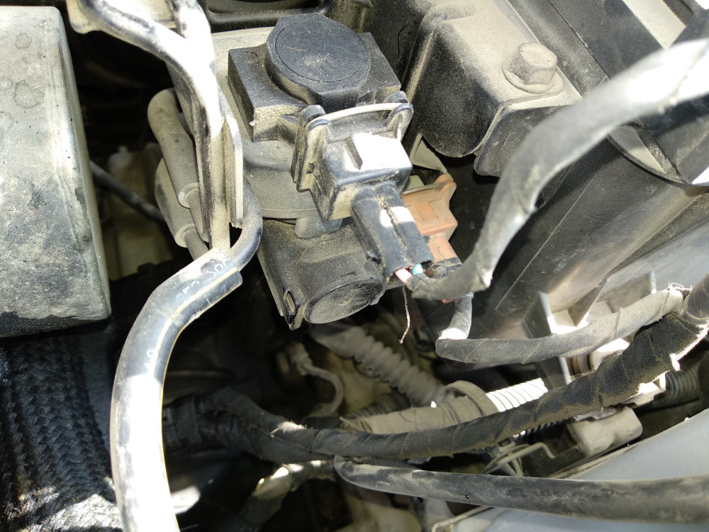
The one with the orange connector on the right is connected directly to some vacuum source. Then there is a hose from there to the solinoid on the left with the black connector. The left solinoid is connected to the turbo actuator. What I'm seeing is that at KOEO there is a 300 kHz square wave with an approximately 70% duty cycle on the left solinoid, ground side switched. On the right solinoid I've got a constant B+ voltage at all times on both wires.
Once I start the engine, the left solinoid shows a duty cycle of about 58%, which is enough to cause the turbo to be active at idle. If I manually depress the actuator arm the turbo spools down completely and MAP drops to about 93 kPa. When I raise the RPMs to about 2500 the duty cycle starts slowly cycling between 50% to 80%, causing the aforementioned MAP oscillations.
So who is a dual solinoid boost control like this supposed to work normally? I'm very suspicious of the fact that I've got a constant B+ voltage on both wires of the right solinoid.
Just some background for context, the engine was rebuilt a few years ago, and there is what seems to be a long standing combustion leak past the injector threads on one cylinder ( the whole injector well is filled with hard carbon build-up ). The car came to me because the owner started hearing a whining noise a few days ago that he said changed with engine speed. I found that the turbo was active at idle ( 16 g/s & 100 kPa MAP ) and that holding at 2500 rpm the turbo actuator was slowly pumping up and down creating a MAP oscillation of between 98 - 130 kPa.
So, there are two solenoids:
The one with the orange connector on the right is connected directly to some vacuum source. Then there is a hose from there to the solinoid on the left with the black connector. The left solinoid is connected to the turbo actuator. What I'm seeing is that at KOEO there is a 300 kHz square wave with an approximately 70% duty cycle on the left solinoid, ground side switched. On the right solinoid I've got a constant B+ voltage at all times on both wires.
Once I start the engine, the left solinoid shows a duty cycle of about 58%, which is enough to cause the turbo to be active at idle. If I manually depress the actuator arm the turbo spools down completely and MAP drops to about 93 kPa. When I raise the RPMs to about 2500 the duty cycle starts slowly cycling between 50% to 80%, causing the aforementioned MAP oscillations.
So who is a dual solinoid boost control like this supposed to work normally? I'm very suspicious of the fact that I've got a constant B+ voltage on both wires of the right solinoid.
Please Log in or Create an account to join the conversation.
- Paul P.
-

- Offline
- Platinum Member
-

Less
More
- Posts: 457
- Thank you received: 195
7 years 6 months ago #23853
by Paul P.
Never stop Learning.
Replied by Paul P. on topic ECU Running Boost at idle and oscillating boost at 2500 rpm
That's interesting! A solenoid should show B+ on both wires only when connected(and OFF), Unplugged, only 1 wire should be B+, the other being the path to GND.
I'm not familiar, nor have any info on this system, but I'm gonna haphazardly guess it needs both solenoids to change the direction of the
actuator arm?
Is it possible only one is a solenoid and the other is PWR feeds for the actuator?(Just thinking out loud on that)
My next question is the vacuum actuation, will the actuator hold vacuum or does it leak down? or with that hose unplugged does the voltage change on either of those two wires you got b+ on?
Id love to see a wiring diagram for this!
Never stop Learning.
Please Log in or Create an account to join the conversation.
Time to create page: 0.253 seconds