2008 Mazda 3 - 2.0L Standard Trans Ignition problem
- jonkirkross
-
 Topic Author
- Offline
- New Member
-

- Posts: 13
- Thank you received: 1
I have a 2008 Mazda 3 2.0L with a standard transmission that was in a front end collision that destroyed parts of the wiring harness, fenders and front clip. We therefore purchased a donor car which is a 2007 Mazda 3 2.0L. We replaced the wiring harness and did have to re-route some of the vacuum lines and sensors to match the 2008 design, however the rest of the install appeared to be the same.
When we attempted to start the car, it did not turn over, all the dash lights came on at first, you could hear relays clicking but the starter never engaged. We were able to engage the starter by putting a jumper cable across the power side of the starter relay in the fuse box, however the car did not actually start. Also, we checked the voltage on the control side of the starter relay with the key turned to the start position and only received a voltage reading of 6V, and from my understanding that relay requires 12V. We then changed over the transmission position sensor, tried the 2007 computer, tried changing the starter relay from the donor as well as the main relay. All to no avail. We also attempted to boost the car thinking that maybe there just wasn't enough juice. Still nothing.
When we do try to start the vehicle, all of the lights on the dash, including the dashboard display go dark. Not sure if this is what is supposed to happen or not.
It appears as though something may not be connected, a fuse could be blown, a wire could be damaged but I am not sure what to check to determine the actual issue with the wiring. What could be causing this to not fire up, it appears to me like we've checked everything that could be contributing to the issue. What diagnostics steps could be taken to actually determine the issue.
Also, I don't think that it is relevant, but we did move over the steering wheel assembly for the air bag, the crash sensor and the airbag control module.
Regards,
Jon
Please Log in or Create an account to join the conversation.
- Tyler
-

- Offline
- Moderator
-

- Full time HACK since 2012
- Posts: 6126
- Thank you received: 1542
For reference, this is the 2007 starting system diagram, manual trans:
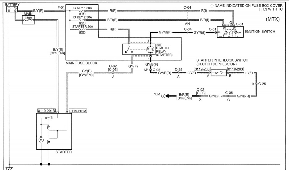
I also looked up the 2008 diagram for comparison, it's identical. The jumper wire across the load side was a good move, so we can concentrate on the control side.
Do you recall which pin you saw 6V on? Or, would you mind retaking your readings? A test light would work for our purposes, too. Connected to B-, pin one should be bright. Connected to B+, pin two should be bright in crank only.
Please Log in or Create an account to join the conversation.
- Paul P.
-

- Offline
- Platinum Member
-

- Posts: 457
- Thank you received: 195
Troubleshooting looks awesome. A couple things bother me on this one and they are super quick checks.
The dimming lights and that 6 volts.
Please do a static voltage reading between B- and the engine block. Should Be Zero
Then take the same reading while jumping the load side of the starter relay.
Just want to verify you have no grounding issues.
The other 6 volts got dropped somewhere, either PWR or GND side
Never stop Learning.
Please Log in or Create an account to join the conversation.
- jonkirkross
-
Topic Author
- Offline
- New Member
-
- Posts: 13
- Thank you received: 1
Please Log in or Create an account to join the conversation.
- jonkirkross
-
Topic Author
- Offline
- New Member
-
- Posts: 13
- Thank you received: 1
Please Log in or Create an account to join the conversation.
- Tyler
-
- Offline
- Moderator
-
- Full time HACK since 2012
- Posts: 6126
- Thank you received: 1542
jonkirkross wrote: So I tested both sides. When the ignition is not in start position, the test light does not illuminate. When we turn the key to start the light does illuminate on the B+ side. So, does that mean the start interlock switch could be faulty? And are there any other diagnostics to perform?
Would you clarify your test results for me? Your test light was connected to B+ and probing pin two at the starter relay socket?
Or, was your test light connected to B- and probing pin one?
Please Log in or Create an account to join the conversation.
- jonkirkross
-
Topic Author
- Offline
- New Member
-
- Posts: 13
- Thank you received: 1
When testing the battery + to pin 2 the light did not illuminate at all.
Please Log in or Create an account to join the conversation.
- jonkirkross
-
Topic Author
- Offline
- New Member
-
- Posts: 13
- Thank you received: 1
And I was incorrect in the dash lights going out when starting, it is only the display on the dashboard that says Hello that goes dark when attempting to start.
Please Log in or Create an account to join the conversation.
- Tyler
-
- Offline
- Moderator
-
- Full time HACK since 2012
- Posts: 6126
- Thank you received: 1542
jonkirkross wrote: We tested the battery - to pin 1 when key is in crank and the light illuminated.
When testing the battery + to pin 2 the light did not illuminate at all.
Gotcha, thanks for the clarification! The ignition switch is working. Now we're going towards the shift interlock or the PCM.
Find the clutch switch under the dash and probe both wires with the test light connected to B+, pedal depressed and key in crank. If the switch is good, both wires will illuminate. If it isn't, only one will illuminate. If the PCM isn't proving a ground, neither will illuminate.
Please Log in or Create an account to join the conversation.
- jonkirkross
-
Topic Author
- Offline
- New Member
-
- Posts: 13
- Thank you received: 1
I also tested ohms and it was infinite resistance when not depressed and showed a closed circuit when closed.
So, the conclusion is that the circuit is good.
What does this conclude? There is an issue with the computer?
Please Log in or Create an account to join the conversation.
- Tyler
-
- Offline
- Moderator
-
- Full time HACK since 2012
- Posts: 6126
- Thank you received: 1542
Now we go towards the PCM and it's powers/grounds/inputs. I don't remember if you said or not - does the check engine light come on with the key on? That'd be a big clue to an inoperative PCM.
Another quick check would be looking for 5V at one of the engine sensors. The camshaft position sensor would be my first choice, being out there in the open and accessible. Disconnect it and check all three wires for voltage with your multimeter, KOEO. At least one should have 5V.
Please Log in or Create an account to join the conversation.
- jonkirkross
-
Topic Author
- Offline
- New Member
-
- Posts: 13
- Thank you received: 1
Please Log in or Create an account to join the conversation.
- Tyler
-
- Offline
- Moderator
-
- Full time HACK since 2012
- Posts: 6126
- Thank you received: 1542
I did some more digging in the wiring diagrams, and found this on the 2008 MY:
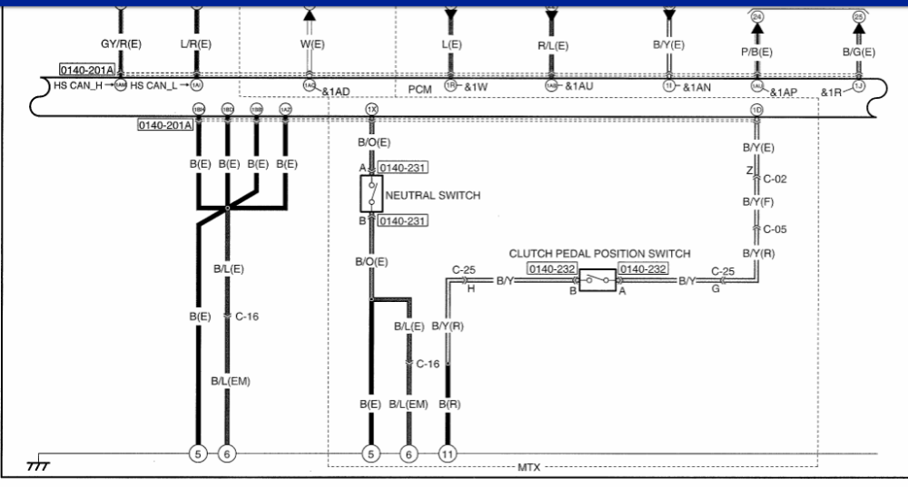
This shows two more switches associated with the manual trans option. Neither is the clutch interlock switch we tested earlier - that one is further up on the same diagram. If the anti-theft light come on and goes out, then I'd be tempted to pursue these switches.
Please Log in or Create an account to join the conversation.
- jonkirkross
-
Topic Author
- Offline
- New Member
-
- Posts: 13
- Thank you received: 1
Connected to the obd2 via elm127 to ODB Fusion. There is a code of an O2 sensor P0138.
Also, it does not pull freeze frame data, I'm assuming that's because it's not running.
Where do I find the other two sensors? The neutral position switch and the clutch pedal position switch?
Thanks for all of your assistance today, I hope we find the issue soon!
Please Log in or Create an account to join the conversation.
- Tyler
-
- Offline
- Moderator
-
- Full time HACK since 2012
- Posts: 6126
- Thank you received: 1542
jonkirkross wrote: The anti-theft light comes on and then goes off.
Super glad to hear this! :silly: I REALLY didn't wanna go down the anti-theft path.
Connected to the obd2 via elm127 to ODB Fusion. There is a code of an O2 sensor P0138.
Also, it does not pull freeze frame data, I'm assuming that's because it's not running.
Also glad to hear this.
Where do I find the other two sensors? The neutral position switch and the clutch pedal position switch?
I wish I knew! :silly: I gotta do some more research on those. I'm honestly not even sure they'll cause a no crank condition. But, I gotta figure the PCM is watching them for some reason...
Thanks for all of your assistance today, I hope we find the issue soon!
Thank YOU! I know this process isn't straightforward, so I appreciate you staying with me.
Please Log in or Create an account to join the conversation.
- Tyler
-
- Offline
- Moderator
-
- Full time HACK since 2012
- Posts: 6126
- Thank you received: 1542
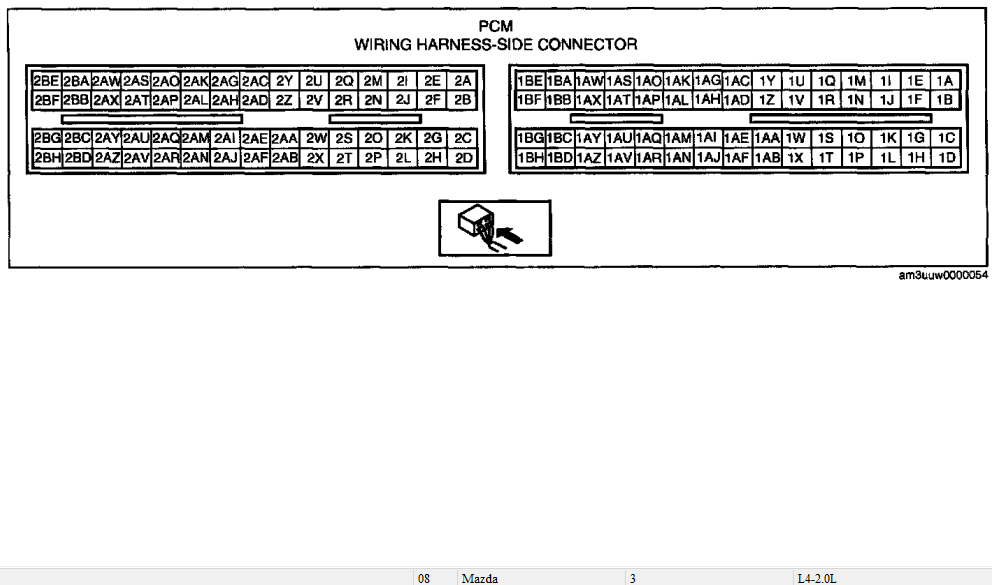
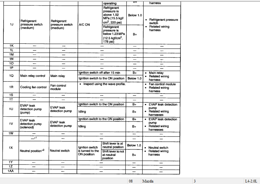
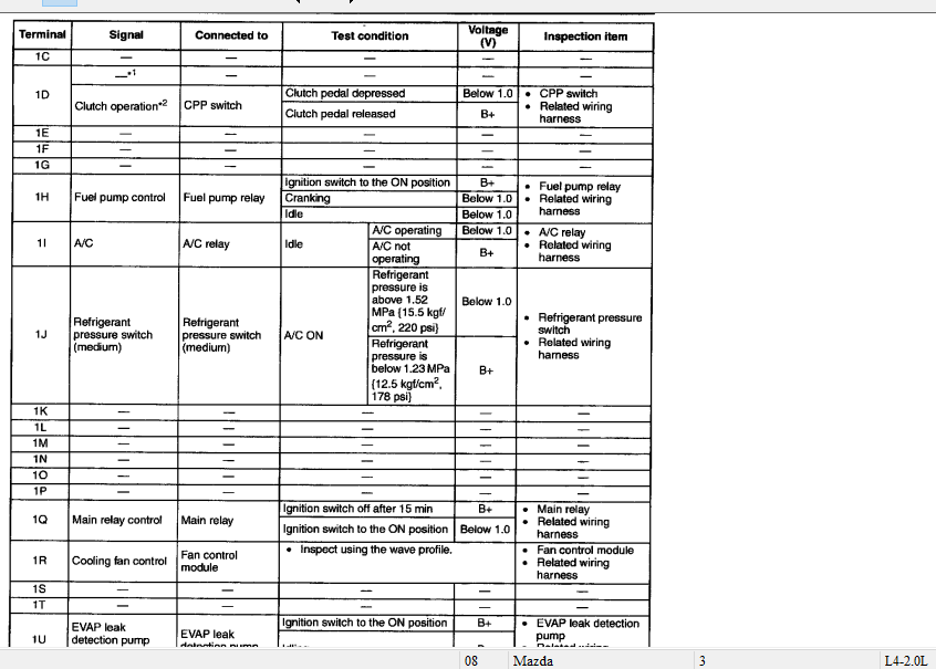
Rather than digging around for the Neutral Switch and the Clutch Pedal Position Switch, I figure it's easier to find the signal wires at the PCM connector and check their operation that way.
Unfortunately, the OE diagrams don't point out pin locations, or have all the PCM pins in numerical order so we could figure out color sequencing. You're looking for a black/orange wire for the Neutral Switch, and a black/yelllow wire for the Clutch Pedal Position Switch. I know, that doesn't narrow it down much. :silly: I can definitely say they're in the same PCM connector (of the two).
They're both going to be pull down switches, so we're looking for 5V or 12V with the switches open, and 0V with them closed. You may have to work the shifter to make the Neutral Switch work. If both change states while working the clutch or shifter, then I'm gonna figure they're working correctly.
Please Log in or Create an account to join the conversation.
- Paul P.
-
- Offline
- Platinum Member
-
- Posts: 457
- Thank you received: 195
Never stop Learning.
Please Log in or Create an account to join the conversation.
- Tyler
-
- Offline
- Moderator
-
- Full time HACK since 2012
- Posts: 6126
- Thank you received: 1542
Noah was also nice enough to hook me up with an alternative diagram. I'll post it up when I get a chance.
Please Log in or Create an account to join the conversation.
- Paul P.
-
- Offline
- Platinum Member
-
- Posts: 457
- Thank you received: 195
Never stop Learning.
Please Log in or Create an account to join the conversation.
- Tyler
-
- Offline
- Moderator
-
- Full time HACK since 2012
- Posts: 6126
- Thank you received: 1542
Less detailed, but way more convenient than surfing through the OE diagram. :lol:
Please Log in or Create an account to join the conversation.