'08 Ram 2500 6.7 No Comm to O2 Module U011A
- ephotrod
-
 Topic Author
- Offline
- New Member
-

- Posts: 14
- Thank you received: 16
Please Log in or Create an account to join the conversation.
- ephotrod
-
Topic Author
- Offline
- New Member
-
- Posts: 14
- Thank you received: 16
Please Log in or Create an account to join the conversation.
- Noah
-

- Offline
- Moderator
-

- Posts: 5028
- Thank you received: 1119
Forgive me if I'm missing something, but there's not a good ground on any of those pins. I'd think at least one would be (much) lower than half a volt.ephotrod wrote: The following are all my readings based on the on demand diagram. A vantage Pro was used on a 20 volt scale 5 ms time base. There are 16 pins all together.
Pin 1: 12.31 volts
Pin 2: 12.31 volts
Pin 3: 2.95 volts
Pin 4: 2.94 volts
Pin 5: 2.86 volts
Pin 6: 2.94 volts
Pin 7: 2.84 volts
Pin 8: 12.35 volts
Pin 9: 12.35 volts
Pin 10: .69 volts
Pin 11: .68 volts
Pin 12: .68 volts
Pin 13: 2.52 volts
Pin 14: 2.52 volts
Pin 15: 2.86 volts
Pin 16: 12.30 volts
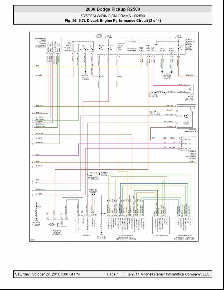
I don't have clean data square waves based on either pin 3 (white) the low data link or pin 11(white and orange) high data link.
The diagram looks bad on my phone, gonna have to fire up the PC, but that's my initial impression.
Please Log in or Create an account to join the conversation.
- Tyler
-

- Offline
- Moderator
-
- Full time HACK since 2012
- Posts: 6124
- Thank you received: 1541
ephotrod wrote: The following are all my readings based on the on demand diagram. A vantage Pro was used on a 20 volt scale 5 ms time base. There are 16 pins all together.
Pin 1: 12.31 volts
...
Yay! :woohoo: Thanks a ton, sir! This is exactly what I was looking for.
Forgive me if I'm missing something, but there's not a good ground on any of those pins. I'd think at least one would be (much) lower than half a volt.
The diagram looks bad on my phone, gonna have to fire up the PC, but that's my initial impression.
Floating ground
") Usually 2.5V, but some Fords use 3.6V (for whatever reason
Usually 2.5V, but some Fords use 3.6V (for whatever reason  ). That's why pins 13 and 14 show 2.52V.
The predictions I made for those pin voltages were hit and miss. I had this pegged for a power-side switched heater, but I think it's actually ground-side switched. Oh well

61 ohms sounds correct. The ECM has a termination resistor and the variable geometry turbo actuator has the second.
It does? :huh: Looking at the diagram again, and it doesn't show the turbo involved:
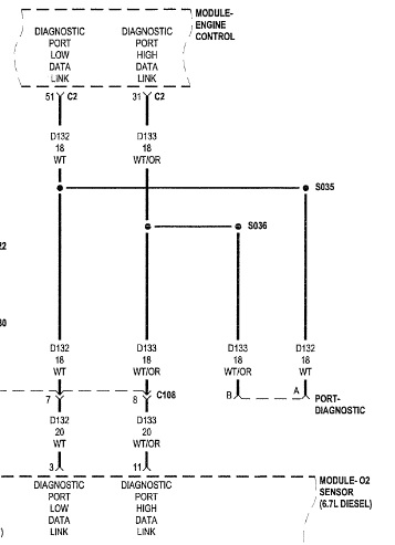
Could be the diagram is wrong?
Please Log in or Create an account to join the conversation.
- Noah
-
- Offline
- Moderator
-
- Posts: 5028
- Thank you received: 1119
Please Log in or Create an account to join the conversation.
- Tyler
-
- Offline
- Moderator
-
- Full time HACK since 2012
- Posts: 6124
- Thank you received: 1541
Noah wrote: The module itself uses a floating ground? I thought that was a signal circuit strategy?
Sorry, I coulda been more specific there :blush: The sensor circuits use a floating ground. Actually, I see what you mean now... Pin 10 is the module ground, with .68V :blink: I didn't look too closely at that one, 'cause ephotrod said he checked module power and ground in the first post.
Maybe it's time to revisit the module ground? :huh:
Please Log in or Create an account to join the conversation.
- Noah
-
- Offline
- Moderator
-
- Posts: 5028
- Thank you received: 1119
Please Log in or Create an account to join the conversation.
- ephotrod
-
Topic Author
- Offline
- New Member
-
- Posts: 14
- Thank you received: 16
Please Log in or Create an account to join the conversation.
- Tyler
-
- Offline
- Moderator
-
- Full time HACK since 2012
- Posts: 6124
- Thank you received: 1541
ephotrod wrote: Would it be alright to use a jumper wire back probe on pin 10 to a chasis ground and see if I have signal then? WHat would be the right way to go about it?
That would work! You could even keep your meter hooked up to the same backprobe and watch the voltage drop down when you add the jumper in. You could also use a test light connected to B+ and touch on the same pin, looking for the light to burn bright. Key on, either way.
If you end up adding a ground, just make sure that the ground your adding is a good ground itself. Then, you can clear the codes and see if anything comes back. If the code doesn't return, then you've found the problem
")
Please Log in or Create an account to join the conversation.
- Noah
-
- Offline
- Moderator
-
- Posts: 5028
- Thank you received: 1119
Please Log in or Create an account to join the conversation.
- Chriscoy
-

- Offline
- Junior Member
-

- Heavy duty truck technician / foreman/ parts guy/
- Posts: 29
- Thank you received: 6
As far as Ohming out the data lines go... Most Cummins engines of the newer vintages uses 2, 120 ohm termination resistors. One is in the ECM, the other is usually in the VGT actuator of the turbocharger. This year may not have the electric turbo actuator on the turbo so this may not be applicable. When both are working and connected in the system, you'll see 60 ish Ohms on the circuit. If one is failing, you'll see it above the 60 ohms.Allow me to remind you that i work on class 8 trucks so Dodge may do it different. Looking at the diagram you put up, they are incomplete views of the ECM. I believe that mitchell has a diagram for the network wiring of most newer cars. I might be wrong but its worth a look.
Again, check your ground wiring, I'm betting that's where you'll find the problem. I'm kinda guessing if the second termination resistor is not in the turbo it might be in that O2 module.
Last thing, Do the squarewaves on the Data lines clear up when you unplug the O2 module? I ask because I had a ISX 15 Cummins that had a shorted VGT actuator crashing the CAN, I was plugged in to the CAN with my scope and when i unplugged the VGT the waveform came back and started looking normal again.
Hope it helps some.
Changing parts is easy, Troubleshooting is an art
Please Log in or Create an account to join the conversation.