06 Chrysler 300 with p0135
- chris.arriazola
-
 Topic Author
- Offline
- Junior Member
-

- Posts: 34
- Thank you received: 2
Please Log in or Create an account to join the conversation.
- Tyler
-

- Offline
- Moderator
-

- Full time HACK since 2012
- Posts: 6124
- Thank you received: 1541
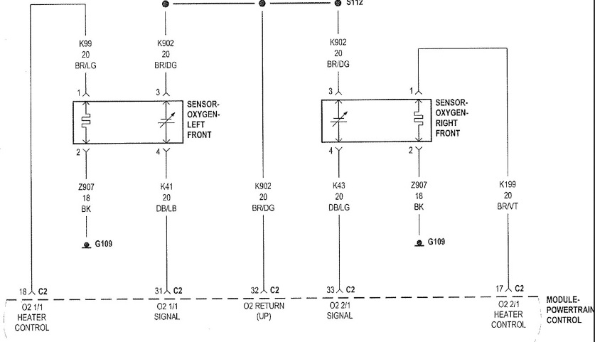
In case anyone's not familiar, these are power-side switched heaters, different from the ground-side switched heaters we're used to on most other makes/models.
I put a scope on heater control on bank 2 to compare with bank 1 and my control drops to 0 volts on my bank 1 when connected to the 02 sensor and rises to 10 volts when disconnected.
Have you tried using a test light on the bank one heater power and ground circuits? I'm asking because what you're saying here is describing a voltage drop in the control circuit. Your resistance test passed, but that doesn't mean there isn't an issue when the circuit is activated. The test light will (hopefully) load the circuit sufficiently to expose any wiring issues. If the test light works, then we may move up to a bigger bulb.
I like the idea of using substitute loads in this case, because I'm not sure how this circuit will behave with a potentially open O2 heater. The PCM controls the power, and it may be using some kind of bias voltage to check circuit integrity before turning the heater driver on. Speaking of, have you tried resistance testing the O2 heater itself?
The multiple cylinder miss may or may not be related to the P0135... Observing scan data during the misfire would determine that. If you haven't seen it already, this ScannerDanner video discusses Chrysler O2's and how picky they can be:
Please Log in or Create an account to join the conversation.
- Noah
-

- Offline
- Moderator
-
- Posts: 5028
- Thank you received: 1119
Tyler beat me to it! I also like the idea of loading the circuit down with a bulb.
Sure looks like a voltage drop issue, since you cut the wire at the PCM, It'd just about have to be in the connector or the PCM itself.
Please Log in or Create an account to join the conversation.
- chris.arriazola
-
Topic Author
- Offline
- Junior Member
-
- Posts: 34
- Thank you received: 2
Please Log in or Create an account to join the conversation.
- Tyler
-
- Offline
- Moderator
-
- Full time HACK since 2012
- Posts: 6124
- Thank you received: 1541
chris.arriazola wrote: I did use a test light to load the circuit but its not as bright as the bank 2. Ive been comparing both on a scope and notice the voltage reading are way different. Both control wires drop voltage but only bank 2 rises to battery voltage bank 1 only reaches 4 volts plugged in and 10 volts un plugged . I also swapped 02 sensors to see if fault moved from 1 to 2 but no change. Im new at testing with scope so want to make sure im testing correctly. Im moving toward a regulator problem in pcm. What you think?
Yep, looks like you're testing it right to me! The 4V plugged in but 10V unplugged is REALLY telling.
Good eye on the test light, too. If you've done the same test at the cut PCM wire, and got the same results, then it sure looks like a PCM. Like Noah said, the last check would be for a burned/spread PCM pin.
Please Log in or Create an account to join the conversation.