*** Restricting New Posts to SD Premium Members ONLY *** (09 May 2025)
Just made a new account? Can't post? Click above.
vehicle: 2011 Cadillac CTS 4 3.6L
- ericblack
-
 Topic Author
- Offline
- New Member
-

- Posts: 9
- Thank you received: 0
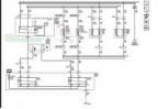
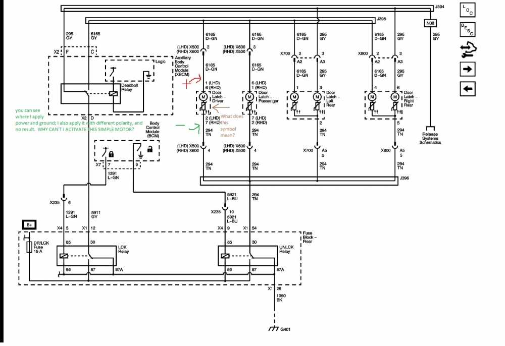
Question: How do you test the door latch? I applied power and ground to dk-g and tan wires (see attachment) and the latch won't operate. I tested the passenger side (known good) in the same manner and still no latch operation by applying power and ground. The only way I can get the latch to operate is by shorting the two micro switches in the exterior door handle mechanism; however, why can't I apply power and ground to the latch and make it operate? The drivers door module pulses the door latch via two relays (see attachment). I can barely see the pulse on my power probe. The pulse seems to be so fast that my test light won't even light (or maybe my bulb resistance is too low). Regardless, it is very difficult to see the power and ground being temporarily supplied. So, looking at the schematic (see attached), the latch is a simple motor; but, I apply power and ground in both polarities and nothing happens? Why? Any ideas?
Please Log in or Create an account to join the conversation.
- ScannerDanner
-

- Offline
- Administrator
-

- Religion says do, Jesus says done!
- Posts: 961
- Thank you received: 498
Mechanically, does that motor latch and unlatch? In other words reverse polarity? The diagram seems to show a constant ground on one side but it's after that other piece in that motor assembly
Don't be a parts changer!
Please Log in or Create an account to join the conversation.
- ericblack
-
Topic Author
- Offline
- New Member
-
- Posts: 9
- Thank you received: 0
The only thing I can think of is that maybe the motor has an electrical "latch" or "enable" system that the schematic is not showing. That is, perhaps there is another input to the latch motor that needs to be met to make the motor work. There is a "deadbolt" relay in the schematic that may play a role in this (i.e. see the Aux control BCM relay has logic inside). Something is missing in the schematic I suspect. I still have the car apart; any ideas as to what to try tomorrow?
Please Log in or Create an account to join the conversation.
- ericblack
-
Topic Author
- Offline
- New Member
-
- Posts: 9
- Thank you received: 0
Please Log in or Create an account to join the conversation.
- ScannerDanner
-
- Offline
- Administrator
-
- Religion says do, Jesus says done!
- Posts: 961
- Thank you received: 498
Never saw one before but is absolutely key in understanding this circuit. That constant ground is for that logic circuit not the motor.ericblack wrote: BTW, have you ever seen that synmbol before just before the motor? Maybe that is important too. Not sure.
Don't be a parts changer!
Please Log in or Create an account to join the conversation.
- ericblack
-
Topic Author
- Offline
- New Member
-
- Posts: 9
- Thank you received: 0
link:
sites.google.com/site/ebautomotiveonline/external-links
Please Log in or Create an account to join the conversation.
- ericblack
-
Topic Author
- Offline
- New Member
-
- Posts: 9
- Thank you received: 0
Please Log in or Create an account to join the conversation.
- Noah
-

- Offline
- Moderator
-

- Give code definitions with numbers!
- Posts: 4916
- Thank you received: 1099
Power Door Lock Deadlock Motors
Some vehicles may be equipped with the deadlock feature, which includes a reversible deadlock motor contained within each door latch assembly. Each deadlock motor is wired to the lock and unlock relays through 2 control circuits; the door lock actuator lock control circuit and the door lock actuator unlock control circuit. To deadlock a door, the door locks are activated by momentarily supplying voltage to the door lock actuator lock control circuits, and ground to the door lock actuator unlock control circuits. The voltage to the door lock actuators is provided through the normally open switch contacts of the theft deterrent alarm relay. To complete the deadlocking, the theft deterrent alarm momentarily energizes an internal relay causing the switch contacts to close applying voltage to the deadlock actuator control circuits for both front and rear doors. Ground to the deadlock actuators is provided through the door lock actuator unlock control circuits. Once the doors are deadlocked, the mechanical lock/unlock linkage within the door lock actuator is physically disconnected so that the door can not be opened even when manually unlocked. If the content theft feature is armed at the same time, the interior door lock switches will not operate the locks.
To undeadlock the doors, the BCM unlocks the doors by momentarily applying ground to the deadlock motor unlock control circuit. This energizes the rear door unlock relay coil causing voltage to flow through the switch contacts to the door lock and deadlock motors. Ground for both motors is supplied through the door lock motor lock circuit through the normally closed contacts of the lock relay to ground.
Driver Door Key Cylinder Switch
"Ground cannot be checked with a 10mm socket"
Please Log in or Create an account to join the conversation.
- Noah
-
- Offline
- Moderator
-
- Give code definitions with numbers!
- Posts: 4916
- Thank you received: 1099
What a roundabout way to open the doors. Good thing batteries never go dead overnight...
"Ground cannot be checked with a 10mm socket"
Please Log in or Create an account to join the conversation.
- ericblack
-
Topic Author
- Offline
- New Member
-
- Posts: 9
- Thank you received: 0
Please Log in or Create an account to join the conversation.
- mwood1164
-

- Offline
- New Member
-
- Posts: 1
- Thank you received: 0
Please Log in or Create an account to join the conversation.