5V ref problem with 1997 Dodge Caravan 3.3L
- Eliud
-
 Topic Author
- Offline
- New Member
-

- Posts: 6
- Thank you received: 0
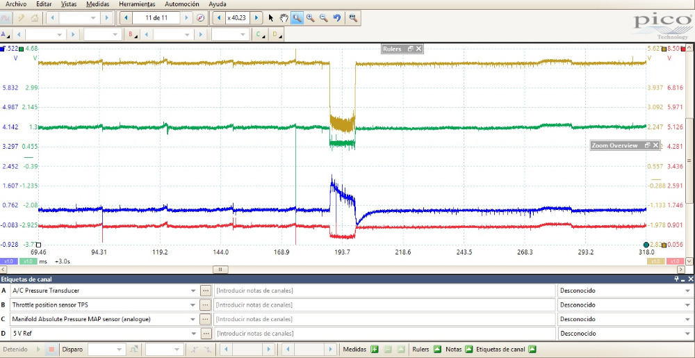
Here is the interesting part.
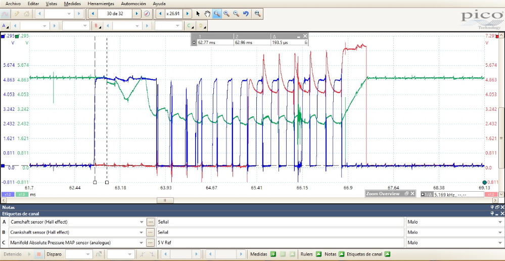
When I scoped the ckp and cmp I found a high voltage at ckp signal wire.
IMG 1.
When I unplugged the ckp sensor the signal voltage returned to 5 V.
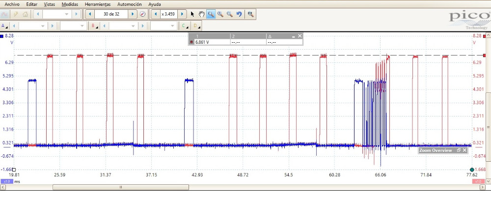
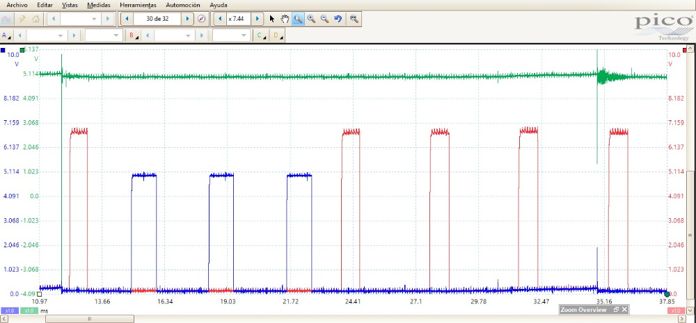
Then I scoped both sensors the moment the van stalled and found this.
IMG 2.
Both sensors where dropping almost at the same time so I figured the 5V or 8V ref circuit had to be involved.
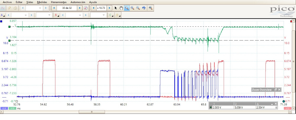
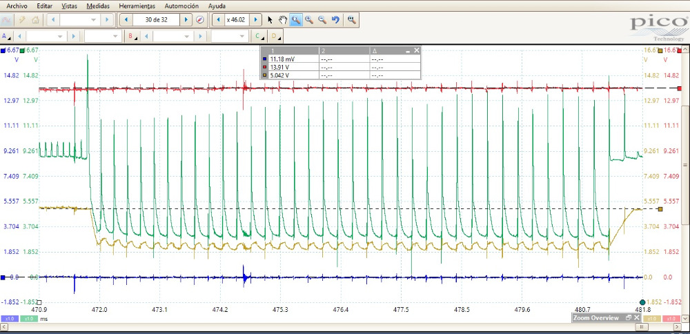
I then repeated the capture when the van stalled this time with the 5 V ref in channel C measured at the MAP sensor.
IMG 3.
The 5 v ref circuit had 2.5 V drop that caused the stall. When the vehicle stalled the MIL started flashing maybe this is a clue?
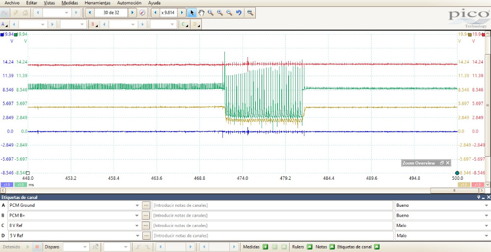
Following the 5V ref fault I scoped the signal from all the sensors that share the 5 V ref externally. The MAP, TPS, and A/C pressure sensor. This is the capture when the engine stalled.
IMG 4.
The A/C pressure sensor acted not as expected so I unplugged it and hoped that somehow fixed the problem… but stall continued. At this point my mind is everywhere.
The last capture is from the PCM power, a ground, the 5 V ref and 8 V feed to cmp and ckp. This capture is when the engine stalled.
IMG 5.
Something is clearly wrong with this readings but I can’t find a way to blame the PCM.
And I can’t understand why in a circuit where only 5 V should be seen, I see 7 V with the sensor plugged in.
Also, I forgot to mention that the ckp signal wire is shared with the tcm so to take this variable off I cut the wire LOL. No change still 7 V ckp signal.
Both ckp and cmp sensors are new.
No dtcs in memory. When stall happens the dtcs caused by testing are erased. Is like the PCM is resetting itself.
Thank you guys for your help.
Kind regards.
Eliud.

Please Log in or Create an account to join the conversation.
- graywave
-

- Offline
- Elite Member
-

- Adv. Diagnostics New Hampshire
- Posts: 303
- Thank you received: 80
I would do some short to ground tests on the Reference wires. Disconnect the pcm and all sensors on the circuit and see if you get continuity to ground when wiggling or moving the harness in different areas
Found this on ALLDATA
PCM REGULATED SENSOR VOLTAGE
Camshaft Position (CMP) Sensor .................... 8.0 Volts
Crankshaft Position (CKP) Sensor .................... 8.0 Volts
Engine Coolant Temperature (ECT) Sensor .................... 5.0 Volts
Manifold Absolute Pressure (MAP) Sensor .................... 5.0 Volts
Throttle Position Sensor (TPS) .................... 5.0 Volts
Vehicle Speed Sensor (VSS) .................... 8.0 Volts
Confirm what it's not, and fix what it is!
Please Log in or Create an account to join the conversation.
- Eliud
-
Topic Author
- Offline
- New Member
-
- Posts: 6
- Thank you received: 0
graywave wrote: I am having some difficulty following your waveforms. Could you elaborate what colors on what diagrams are what sensors and what part of the circuit? I can understand a couple but the other waveforms don't elaborate on what is what.
I would do some short to ground tests on the Reference wires. Disconnect the pcm and all sensors on the circuit and see if you get continuity to ground when wiggling or moving the harness in different areas
Found this on ALLDATA
PCM REGULATED SENSOR VOLTAGE
Camshaft Position (CMP) Sensor .................... 8.0 Volts
Crankshaft Position (CKP) Sensor .................... 8.0 Volts
Engine Coolant Temperature (ECT) Sensor .................... 5.0 Volts
Manifold Absolute Pressure (MAP) Sensor .................... 5.0 Volts
Throttle Position Sensor (TPS) .................... 5.0 Volts
Vehicle Speed Sensor (VSS) .................... 8.0 Volts
Thank you for pointing that out.
I'll try to explain better next time.
IMG 1
Yellow Channel : CKP signal
Pink Channel: CMP signal
IMG 2
Blue channel: CMP signal
Red channel: CKP signal
IMG 3
Blue channel: CMP signal
Red channel: CKP signal
Green channel: 5V ref (measured at MAP connector)
IMG 4
Blue channel: A/C pressure sensor signal
Red channel: TPS sensor signal
Green channel: MAP signal
Yellow channel: 5V ref (measured at A/C pressure sensor connector)
IMG 5
Blue channel: PCM ground
Red channel: PCM B+
Green channel: 8 V
Yellow channel: 5 V ref
(all measured at PCM connector)
Please Log in or Create an account to join the conversation.
- graywave
-
- Offline
- Elite Member
-
- Adv. Diagnostics New Hampshire
- Posts: 303
- Thank you received: 80
What is interesting is both the 8v ref and 5v ref are being pulled down at the same time. I would assume these are both completely different circuits in the PCM and would expect one or the other to fault, but not both. The 8v ref is extremely noisy before it craps out too and it doesn't just get pulled down, I see it spike to batt voltage and switch up and down a lot.
I am not too concerned with a bad ground to the sensors as all the signals are being pulled to ground but it seems they do rest around 800mv at the ground level?
What I am concerned with is the 8v ref is not reaching 8v at any time in the ckp/cmp signals and the CKP And CMP signals have different signal voltages when they are both supplied the same 8v ref in the first image below.
Im curious if inside the PCM, if the 8v and 5v ref are from the same feed circuit and connected in such a way where if one ref was shorted out it would effect the other.
I wonder if other reference circuits are affected by this. I would scope the engine coolant temp sensor as this has its own dedicated 5v ref voltage next time you want to test drive it. Curious if it craps out too. This might be a way of condoning the PCM. Maybe even scope the Vehicle Speed Sensor ref as that is a 8v ref
What I am seeing, and let me know if you see this too in the picture below, I am seeing the 5v (green) being pulled down at the same time the CMP Signal spikes up to 5v and then both have a similar pattern till the issue goes away. We both know that the CMP and CKP are supposed to have 8v refs, not 5v refs. Maybe something is shorted. I also see the CKP (red) signal has some odd anomalies when the event is not occurring. At the tops of the rise, you see shark fines, almost like the voltage is getting pulled back down, maybe the 8v source is not strong enough to bring the signals to 8v, either due to a fault in the ref wire or a fault in the signal wire.
Some tests I would want to do from looking at everything. PCM, TCM and sensors unplugged. Let me know if you feel these are valid (Not in any specific order)
1. Short to Ground on 5v ref, 8v ref and Signal Wires
2. Continuity Tests (Short Test) between 5v to 8v ref wires
3. Continuity Tests between 5v ref and CMP signal wire. Looks like CMP might only be going to 5v when in operation?
4. I noticed the TPS signal goes to the TCM too. MAYBE de-pin or cut this wire?? I would do this last if you think the TCM might be shorting the signal. If that were true though, I would assume the TPS signal in the TCM Data list would go array.
What does the Live Data Show during this events?
I learned from my Nissan Altima Case Study that leaning on the fact its temp related can really throw you in the wrong direction or at least make you second guess an obvious fact.
Also in the image below, how in the hell does the 8v ref get pulled to system voltage? I see the PCM B+ and Ground both are affected by the event too which is interesting.
Seeing that I would want to make sure there is not short to power on the 8v REF wire. It confuses the hell out of me as to why the 8v ref would go to system voltage and then down to 2.8v, at times to 0v. My thoutht is, if this was strictly shorted to power, then we would see the line jump from 8v to system voltage and back down to 8v. If it was shorted to ground then we would see the line drop from 8v to 0v and back to 8v. Why both way?
The other thing I see is just before the event happens, you see the 8v ref, spike to system voltage twice but it returns to 8.6v....this tells me a short to power issue. You can also see during the very first spike in the 8v ref, is it looks like the B+ source is being pulled down at the exact time to 8v ref voltage.
Do you still have the live scope file for this capture? Basically I want to separate the channels more so I can see the detail. It looks like the red and green channel during the first spike are mixed together which is why it looks like the red trace goes down to 8v and the green goes to system voltage.
Confirm what it's not, and fix what it is!
Please Log in or Create an account to join the conversation.
- Eliud
-
Topic Author
- Offline
- New Member
-
- Posts: 6
- Thank you received: 0
I am not too concerned with a bad ground to the sensors as all the signals are being pulled to ground but it seems they do rest around 800mv at the ground level?
I threw a cursor to measure V of ckp and cmp signals when pulled to ground and it reads 137 mV. A bit high you are right. Is this where you see a high ground voltage?
What I am seeing, and let me know if you see this too in the picture below, I am seeing the 5v (green) being pulled down at the same time the CMP Signal spikes up to 5v and then both have a similar pattern till the issue goes away. We both know that the CMP and CKP are supposed to have 8v refs, not 5v refs. Maybe something is shorted. I also see the CKP (red) signal has some odd anomalies when the even t is not occurring. At the tops of the rise, you see shark fines, almost like the voltage is getting pulled back down, maybe the 8v source is not strong enough to bring the signals to 8v, either due to a fault in the ref wire or a fault in the signal wire.
This is a zoomed view of the event. The CMP signal (blue) goes to 5 V then the 5 V ref (green) fails some micro seconds later.
I also went back to the buffer to take a closer look at the ckp signal (red) and you have a good point! it's very different from the top of the cmp signal (blue) rise. I also found some weird noise on 5 V ref (green). Is this noise ignition related?
Years ago I did a known good capture of this vehicle ckp-cmp sync.
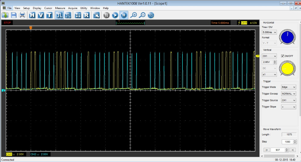
Both CKP (blue) and CMP (yellow) have 5 V signals being pulled down by the sensor. Thats why I think that in my new captures the 7 V signal from the CKP (red) is bad while the 5 V signal from the CMP (blue) is good.
My understanding of the ckp and cmp sensor circuit for this vehicle is like this and correct me if im wrong.
Both CMP and CKP sensors share a 8V feed, a ground and both have pull-down designs. So the PCM feeds 5 V to the signal wires which are grounded by the sensors to make the square wave. When the CKP sensor (red) is plugged it produces a 7 V square wave but when its unplugged the voltage in the signal wire returns to 5 V. How can this happen? and also why the shark teeth noise? I agree with you it should be a short to power of some sort.
The CKP sensor was replaced but 7 V signal is still present.
Some tests I would want to do from looking at everything. PCM, TCM and sensors unplugged. Let me know if you feel these are valid (Not in any specific order)
1. Short to Ground on 5v ref, 8v ref and Signal Wires
2. Continuity Tests (Short Test) between 5v to 8v ref wires
3. Continuity Tests between 5v ref and CMP signal wire. Looks like CMP might only be going to 5v when in operation?
4. I noticed the TPS signal goes to the TCM too. MAYBE de-pin or cut this wire?? I would do this last if you think the TCM might be shorting the signal. If that were true though, I would assume the TPS signal in the TCM Data list would go array.
I agree with tests 1, 2 and 4. Those tests will rule out wiring problems.
Im not sure if I understand test 3.
Also a continuity test between 8V and B+.
I'll do them and report my findings back to you as soon as possible.
What does the Live Data Show during this events?
I don't have live data recordings. I'll save recordings from all sensors that share the 5 V ref and post them here.
Also in the image below, how in the hell does the 8v ref get pulled to system voltage? I see the PCM B+ and Ground both are affected by the event too which is interesting.
Seeing that I would want to make sure there is not short to power on the 8v REF wire. It confuses the hell out of me as to why the 8v ref would go to system voltage and then down to 2.8v, at times to 0v. My thoutht is, if this was strictly shorted to power, then we would see the line jump from 8v to system voltage and back down to 8v. If it was shorted to ground then we would see the line drop from 8v to 0v and back to 8v. Why both way?
The other thing I see is just before the event happens, you see the 8v ref, spike to system voltage twice but it returns to 8.6v....this tells me a short to power issue. You can also see during the very first spike in the 8v ref, is it looks like the B+ source is being pulled down at the exact time to 8v ref voltage.
This is a closer look of the event. I too don't have a clue of what can cause the voltage to go up and down.
The razor shaped noise is present in 8v ref (green) before the event and goes away once the vehicle stalls. Noise amplitude is 1.135 V.
8V regulator failing??
Please Log in or Create an account to join the conversation.
- Eliud
-
Topic Author
- Offline
- New Member
-
- Posts: 6
- Thank you received: 0
Do you still have the live scope file for this capture? Basically I want to separate the channels more so I can see the detail. It looks like the red and green channel during the first spike are mixed together which is why it looks like the red trace goes down to 8v and the green goes to system voltage.
Im trying to upload it but the file size is very large.
How can we get around this problem?
Please Log in or Create an account to join the conversation.
- graywave
-
- Offline
- Elite Member
-
- Adv. Diagnostics New Hampshire
- Posts: 303
- Thank you received: 80
I do need to look at some reference material. I just learned something new in your thread and that is older Chryslers seems to use 2 separate reference voltages for the crank and cam sensor. 8v feed to the sensors, but a 5v signal supply to the sensor as the pull down. I got mislead by the material I was reading and did have some confusion when you mentioned it was a 5v pull down. With that said, I need to do some research before giving some more advice.
Regardless though, I don't like the 8v ref being pulled up to system voltage. I did watch a video from Mr. Danner and he had mentioned since the VSS is supplied with the same 8v ref, apparently it has a history of shorting the 8v ref out and disabling the vehicle. I don't exactly see that in your pictures, but I do see the 8v ref being pulled to around 2.5v. Maybe that is the regulator grounding the reference to try and bring the voltage back down and it is just a circular effect. In the wiring diagrams I have, I see the "Output Shaft Speed Sensor OSSS" leading to the TCM which then sends a VSS Signal to the PCM. The OSSS has a power and ground. The power I am guessing is 8v?
I'll post again soon but this is where knowing PCM internal circuit design would really be beneficial. I have a theory but that is all it is and I"ll edit your picture so you can understand what im talking about more. I am really hoping someone with more electrical engineering background can chime in and correct me if I am way off in left field. Maybe I am thinking to much here too and making it more complicated than it has to be. My theory is, that the 5v REF is regulated off of the 8v REF. Meaning, if the 8v REF is shorted to power (regardless of how or where) and the regulator see this, grounds the circuit or does what it needs to in order to bring the circuit back down to 8v, is it possible it can bring it to far below 8v and will then drop the 5v REF??
Here are the wiring diagrams I am looking at. I uploaded the PDF to my google drive. Easier than spending lots of time to make an image that is displayed correctly on the forum.
They are for a 1997 Dodge or Ram Truck Caravan FWD V6-201 3.3L VIN R MFI
drive.google.com/file/d/1pq17OnJBBmd46Y1...1Xn/view?usp=sharing
Video I was talking about
Confirm what it's not, and fix what it is!
Please Log in or Create an account to join the conversation.
- graywave
-
- Offline
- Elite Member
-
- Adv. Diagnostics New Hampshire
- Posts: 303
- Thank you received: 80
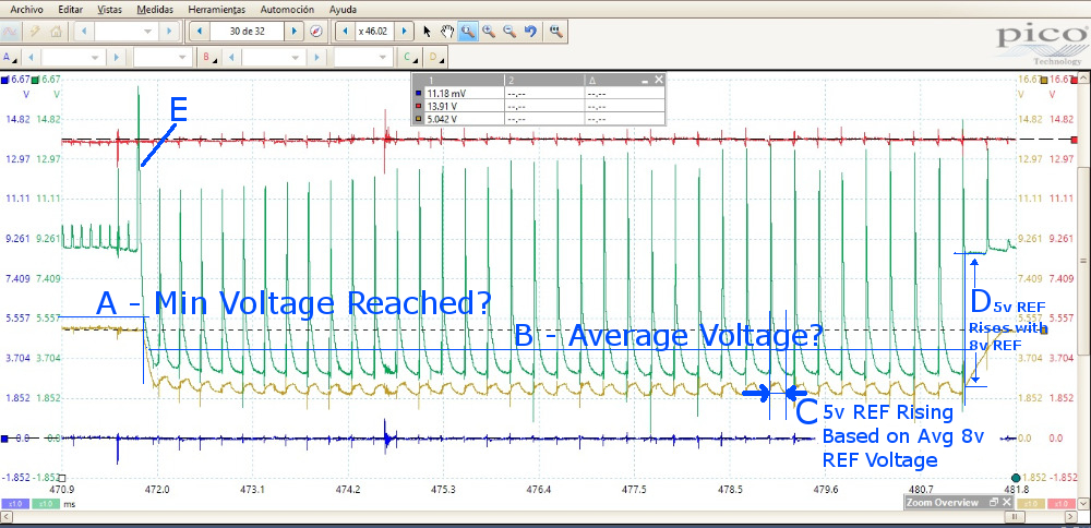
I edited your image below to try and explain my theory. You can see at the point of "A", this might be the minimum working voltage for the 5v regulator. Seems source voltage would be around 5.5v when the 5v REF starts to drop out. "B" seems roughly where an average voltage would be for the 8v REF circuit. "C" is rises in the 5v REF based on the 8v REF average voltage increase. As soon as 8v REF stabilizes to proper voltage, the 5v ref immediately starts to climb to proper voltage.
So I am certainly pointing my finger at the 8v REF circuit.
I agree with tests 1, 2 and 4. Those tests will rule out wiring problems.
Im not sure if I understand test 3.
Also a continuity test between 8V and B+.
I'll do them and report my findings back to you as soon as possible.
I added 3 when I thought we were looking for a 8v signal coming back. Not 5v. When I saw an 8v ref signal going to the cmp & ckp I automatically thought we should see a 8v signal. So ignore that.
In the image below, The CKP is around 7v and I am wondering if the CKP is shorting internally? I Also don't know why that would read 7v if its normally supposed to read 5v unless its shorting inside. Doesn't exactly explain the system voltage rise on the 8v REF which is located at "E" in the above image. Im curious if you have defective CKP or CMP sensors.
When were the CMP and CKP sensors replaced and what reason was there for their replacement? Will this vehicle run with only CMP or only CKP?
Confirm what it's not, and fix what it is!
Please Log in or Create an account to join the conversation.
- juergen.scholl
-

- Offline
- Platinum Member
-

- Active partschanger
- Posts: 1233
- Thank you received: 462
An expert is someone who knows each time more on each time less, until he finally knows absolutely everything about absolutely nothing.
Please Log in or Create an account to join the conversation.
- graywave
-
- Offline
- Elite Member
-
- Adv. Diagnostics New Hampshire
- Posts: 303
- Thank you received: 80
Confirm what it's not, and fix what it is!
Please Log in or Create an account to join the conversation.
- juergen.scholl
-
- Offline
- Platinum Member
-
- Active partschanger
- Posts: 1233
- Thank you received: 462
An expert is someone who knows each time more on each time less, until he finally knows absolutely everything about absolutely nothing.
Please Log in or Create an account to join the conversation.
- graywave
-
- Offline
- Elite Member
-
- Adv. Diagnostics New Hampshire
- Posts: 303
- Thank you received: 80
Interested to know what you find!
")
I found the following pins.
PIN 6: B+ FROM ASD RELAY (DKGRN/ORG)
PIN 10: Ground (BLK/TAN)
PIN 20: B+ START/RUN (WHT/BLK)
PIN 46: B+ (RED/WHT)
PIN 50: GROUND (BLK/TAN)
Confirm what it's not, and fix what it is!
Please Log in or Create an account to join the conversation.
- Eliud
-
Topic Author
- Offline
- New Member
-
- Posts: 6
- Thank you received: 0
graywave wrote: You are correct. My initial look at the wiring diagram fooled me. This could be a game changer as i was initially thinking a power ground issue at pcm but missed thise other pins.
Interested to know what you find!
I found the following pins.
PIN 6: B+ FROM ASD RELAY (DKGRN/ORG)
PIN 10: Ground (BLK/TAN)
PIN 20: B+ START/RUN (WHT/BLK)
PIN 46: B+ (RED/WHT)
PIN 50: GROUND (BLK/TAN)
I missed those pins! Thank you for pointing that out.
I tried to capture the event 2 days in a row but the vehicle now won´t stall.
I saw normal voltage readings at pin 6, 20, and 46. (Battery voltage)
PCM Grounds at pins 10, 50 and sensor ground pin 43 all under 33 mV.
All readings at normal engine operation.
I also checked for opens and shorts between 8Vref and 5Vref, 8Vref and ground, 8Vref and B+, 5Vref and ground, 5Vref and B+ and even 8Vref with all other pins on PCM.
I did test with all sensors, TCM and PCM unplugged.
All wiring tests good.
CKP and CMP were replaced about a week ago in an attempt to fix the stall issue and the 7V CKP signal.
I think the high ckp signal voltage is related to the noise in 8V ref circuit... but why it’s not affecting the cmp signal??
About the VS Signal ok, so I see it comes from the OSS sensor. This sensor is a two wire variable reluctance sensor ??? or a magneto resistive sensor?
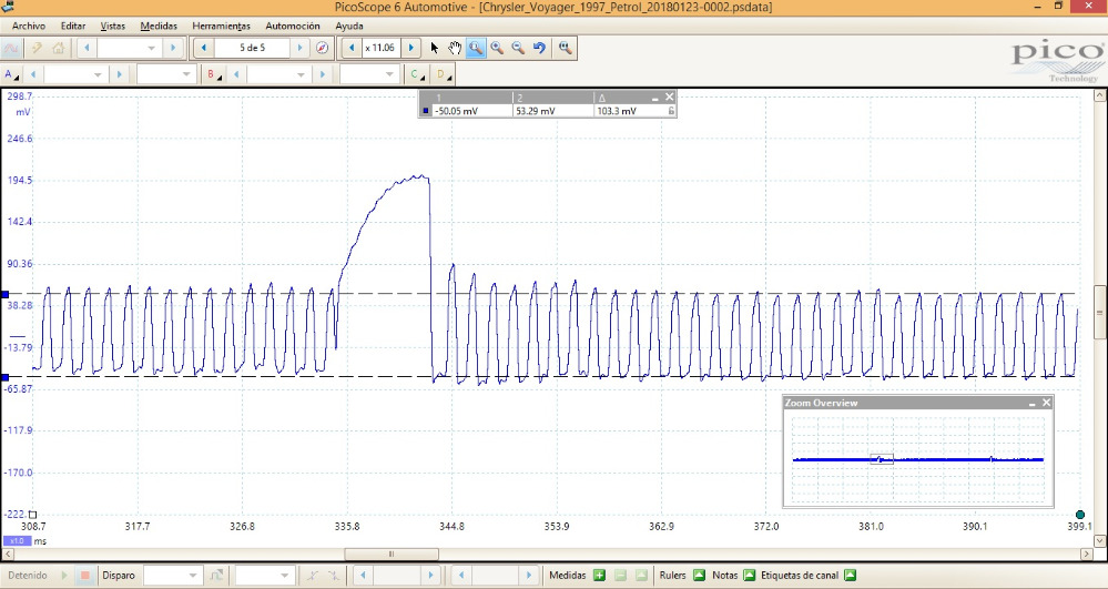
This is a capture of the OSS sensor signal with negative lead on battery ground. I’m not very familiar with this type of signal

If the sensor is a VRS how is the 8Vref involved if those sensors produce voltage?
Please Log in or Create an account to join the conversation.
- graywave
-
- Offline
- Elite Member
-
- Adv. Diagnostics New Hampshire
- Posts: 303
- Thank you received: 80
So, I don't have any other suggesting at the moment. I know bad powers or grounds can cause some really crazy stuff to happen especially intermittent problems. Could a bad PCM ground cause the 8v regulator to malfunction? In my mind, absolutely. Could a bad power cause a 8v regulator to malfunction, I think it could. The spike surges we were seeing might have been caused by a bad ground or power, allowing the regulator to be switched on and off rapidly. This is where my knowledge on circuit design starts to send me sideways. Now why didn't we see the same thing happen with the 5v voltage? I can't explain that completely but I'll expand my theory below
I did some reading and watching of videos about voltage regulators. If they use a 3 pin linear voltage regulator, Pin 1 as INPUT Unregulated Voltage, Pin 2 as GROUND and pin 3 as REGULATED OUTPUT (may not be that order), then if the regulator looses its ground, the regulator may not be able to measure the difference in voltage correctly and might allow system voltage (unregulated voltage) to pass through. Without a ground, there is I guess, bias current that may bounce within the regulator which could cause the up and down spikes we saw? I would think something like that though would be more of an oscillation like in a ignition coil at the end of spark. Again don't quote me on that but this is my light understanding. Now going from 13.5v to 8v is more efficient than going from 13.5v to 5v. So using a linear voltage regulator on the 8v regulated output might be more efficient at creating the 5v REF circuit as there is less of a voltage drop. This would make sense seeing the the waveform below as linear voltage regulators have a minimum working voltage and explain it as linear drop out voltage. The 5v regulators I have seen online have a 2v drop out voltage meaning the regulator needs at least 7v to work properly. Those same 2v drop out regulators may be able to handle lower voltages and stay running properly. I am sure the documented drop out voltage even has an error tolerance. Now in the image below, you can see that its possible, if the circuit is designed how I think, that the drop out voltage of the 5v regulator could be less or maybe we just don't see enough detail to get an accurate representation of where the 5v started to drop at in comparison to the minimum 8v ref voltage reached.
So could a bad ground be the culprit? I think so. Could a bad power feed cause an internal relay or some sort of ground control device to deactivate and cause an internal ground problem to the regulator and cause the same issue? I think so. If we had a bad, low power feed to the regulator, you would see the output regulated voltage become unregulated and continue to drop to a certain point. If we lost the power feed, we would also loose the regulated voltage output. See how I am thinking of a ground issue?
I'll list what I don't like and hopefully this will be some food for thought in terms of direction. If I think of anything I'll let you know.
1. 8v REF Signal rising to system voltage during the event (Finger Pointed Here)
2. 7v Crank signal on a 5v signal wire. Disconnecting crank sensor allows voltage to return to 5v. I would check continuity between the signal pin and power feed pin on the crank sensor. I don't think there should be any continuity. Maybe even disconnect the crank sensor, manually apply power and ground to ground and power pin and see if you measure a voltage output on the signal pin. Just wondering if there is in fact voltage leaking (Could become a problem but "may" not be the culprit)
3. 5v REF dropping at same time 8v REF wigs out. (Thinking an effect of the 8v REF problem)
Confirm what it's not, and fix what it is!
Please Log in or Create an account to join the conversation.
- graywave
-
- Offline
- Elite Member
-
- Adv. Diagnostics New Hampshire
- Posts: 303
- Thank you received: 80
If anyone else out there has some idea or if I had given some misinformation, please by all means correct me.
Confirm what it's not, and fix what it is!
Please Log in or Create an account to join the conversation.
- juergen.scholl
-
- Offline
- Platinum Member
-
- Active partschanger
- Posts: 1233
- Thank you received: 462
An expert is someone who knows each time more on each time less, until he finally knows absolutely everything about absolutely nothing.
Please Log in or Create an account to join the conversation.
- Eliud
-
Topic Author
- Offline
- New Member
-
- Posts: 6
- Thank you received: 0
juergen.scholl wrote: Possible user error? ? Ground loops? ? As your dealing with VR sensors make sure not to hook up to bòth wires of one sensor while you're using more than one channel....use one common ground for all channels.
I was using only channel A. Negative lead to battery ground and positive lead to TCM connector pin 14 output speed signal.
This is the same capture with a 1 khz low pass filter. Is this a bad capture? Is I said before I'm not very familiar with VRS signals.
A 1kHz low pass filter is too much? I'm not very familiar with those features.
Please Log in or Create an account to join the conversation.
- graywave
-
- Offline
- Elite Member
-
- Adv. Diagnostics New Hampshire
- Posts: 303
- Thank you received: 80
I don't know if that was just a fluke or associated with the problem you are having, but more repetition would be good in that capture. More time base to see if that ramp occurs more often. More curiosity than anything, I don't think this is the direction to go for the diagnosis but I see a possible problem, so it should be investigated to see where it leads.
Mr. Danner has a video regarding this type of sensor used as a wheel speed sensor
Another quick little video
Confirm what it's not, and fix what it is!
Please Log in or Create an account to join the conversation.