2009 Dodge Caliber sxt Canadain car with 2.0 auto wouldnt turn off with key.
- Hydo
-
 Topic Author
- Offline
- New Member
-

- Ehh
- Posts: 7
- Thank you received: 0
2009 Dodge Caliber2.0 sxt umph..
About a month ago my daughter car wouldnt start intermittently unless we removed the ground cable and put it back on well one day it wouldnt turn off with key removed or remote starter.
I got car shutoff with unplugging the immobilzer bypass,now it wont start or turnover at all but all dash lites and head lites working fine,checked relays under drivers side fender,I removed the remote starter,checked all fuses all good.
Fuse #21 on the Tipm dead period.Its for the IOD Feed Intrus Mod/Siren (If Equipped).Almost forgot battery and starter working good.
Any help would be awsome.
Thanks
Please Log in or Create an account to join the conversation.
- arbez
-

- Offline
- Premium Member
-

- Posts: 150
- Thank you received: 53
www.revbase.com/BBBMotor/Wd/DownloadPdf?id=169820
It has that evil, 4 letter word (TIPM), in it that causes all kinds of issues.
Do you have a starter fuse and/or relay in the TIPM? If so, we can do some testing from there.
Please Log in or Create an account to join the conversation.
- Hydo
-
Topic Author
- Offline
- New Member
-
- Ehh
- Posts: 7
- Thank you received: 0
Please Log in or Create an account to join the conversation.
- graywave
-

- Offline
- Elite Member
-

- Adv. Diagnostics New Hampshire
- Posts: 303
- Thank you received: 80
Not shutting down with the key is pointing me toward a bad ignition switch or bad/no output from the ignition switch. You could check a wiring diagram for fuses that are "HOT IN RUN" to see if those still have power after the key is cycled off. Regardless I would need to pull a wiring digram for the ignition switch circuit and start metering the switch.
Was it possible the remote start button was pressed before the key was removed? I know you had mentioned it wouldn't shut down even with the remote start so in theory that answers the question.
Confirm what it's not, and fix what it is!
Please Log in or Create an account to join the conversation.
- arbez
-
- Offline
- Premium Member
-
- Posts: 150
- Thank you received: 53
I think you should elaborate on what you have disconnected, disabled or bypassed. Likely that this is at least part of your problems.
I would chase the no crank first & hope that is related to your other issues. Once we get it cranking, than we need to see why it wont stay running.
Please verify if you have a independent starter relay. Then we can go from there.
TIPM is a four letter word
Please Log in or Create an account to join the conversation.
- arbez
-
- Offline
- Premium Member
-
- Posts: 150
- Thank you received: 53
I'm pretty sure I've done starter relay bypasses on these also. Not necessarily a Caliber, but some Chrysler or VW car/truck/van/thing/it.
Check & see if yours has a separate relay. AllData could be wrong (that never happens).
Also, do you have an aftermarket alarm?
Please Log in or Create an account to join the conversation.
- Hydo
-
Topic Author
- Offline
- New Member
-
- Ehh
- Posts: 7
- Thank you received: 0
As for Immobilzer its lite comes one for a few secs then turns off,factory remote for doors works like it should.I dont know of a any factory alarm but it does have a panic button on the remote.
No aftermarket crap at all on the car.I was told the starter relay is in under fender but if it isnt please let me know for sure,I will keep searching for info.
One more thought when i turn the key to start position all my dash lites stay on is the normal for these crappy cars,The car is outside in freezing tempatures and at my daughters so will keep trying to figure this car out.
Thanks for your assistance.
Please Log in or Create an account to join the conversation.
- Hydo
-
Topic Author
- Offline
- New Member
-
- Ehh
- Posts: 7
- Thank you received: 0
What is this ?
Please Log in or Create an account to join the conversation.
- graywave
-
- Offline
- Elite Member
-
- Adv. Diagnostics New Hampshire
- Posts: 303
- Thank you received: 80
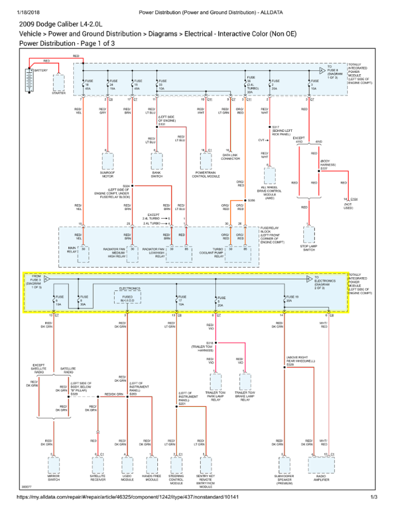
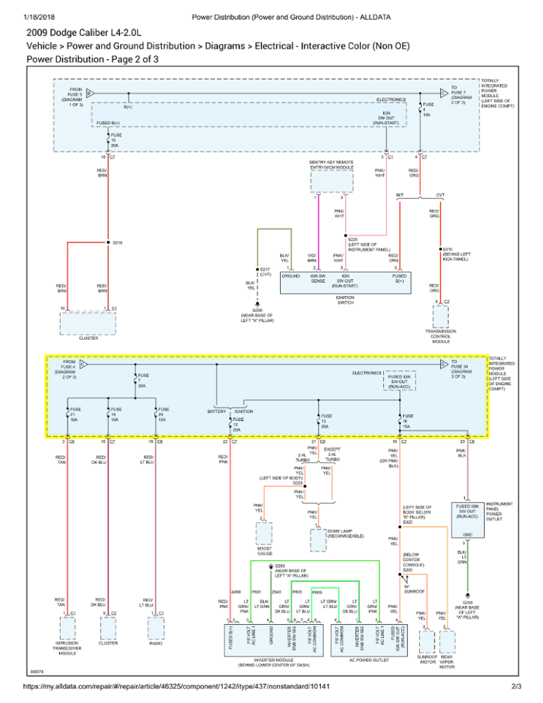
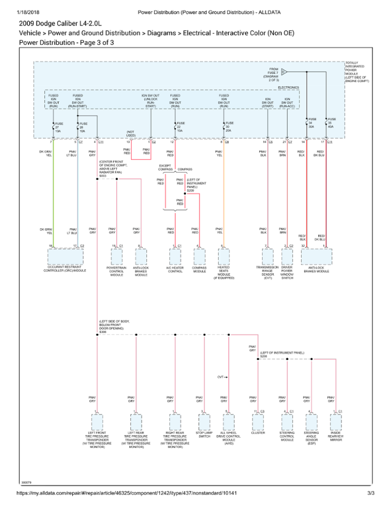
IOD is the Ignition Off Draw circuit. Used to supply power to many different modules. During shipment fuses 7 and 8 are removed to reduce battery drain.
Operation from ALLDATA
OPERATION
The term ignition-off draw identifies a normal condition where power is being drained from the battery with the ignition switch in the Off position. The IOD fuse feeds the memory and sleep mode functions for some of the electronic modules in the vehicle as well as various other accessories that require battery current when the ignition switch is in the Off position, including the clock. The only reason the IOD fuse is disconnected is to reduce the normal IOD of the vehicle electrical system during new vehicle transportation and pre-delivery storage to reduce battery depletion, while still allowing vehicle operation so that the vehicle can be loaded, unloaded and moved as needed by both vehicle transportation company and dealer personnel.
The IOD fuse is disconnected from Totally Integrated Power Module (TIPM) fuse cavities 7 and 8 in a preset fuse holder. when the vehicle is shipped from the assembly plant. Dealer personnel must reconnect the IOD fuse when the vehicle is being prepared for delivery in order to restore full electrical system operation. Once the vehicle is prepared for delivery, the IOD function of this fuse becomes transparent and the fuse that has been assigned the IOD designation becomes only another Fused B(+) circuit fuse. The IOD fuse serves no useful purpose to the dealer technician in the service or diagnosis of any vehicle system or condition, other than the same purpose as that of any other standard circuit protection device.
The IOD fuse can be used by the vehicle owner as a convenient means of reducing battery depletion when a vehicle is to be stored for periods not to exceed about thirty days. However, it must be remembered that disconnecting the IOD fuse will not eliminate IOD, but only reduce this normal condition. If a vehicle will be stored for more than about thirty days, the battery negative cable should be disconnected to eliminate normal IOD; and, the battery should be tested and recharged at regular intervals during the vehicle storage period to prevent the battery from becoming discharged or damaged.
Confirm what it's not, and fix what it is!
Please Log in or Create an account to join the conversation.
- graywave
-
- Offline
- Elite Member
-
- Adv. Diagnostics New Hampshire
- Posts: 303
- Thank you received: 80
When you turn your key on to the RUN position, does the engine light turn on? If so, at least the computer is technically powered up, if not could be a power issue.
Starting and Charging Circuit
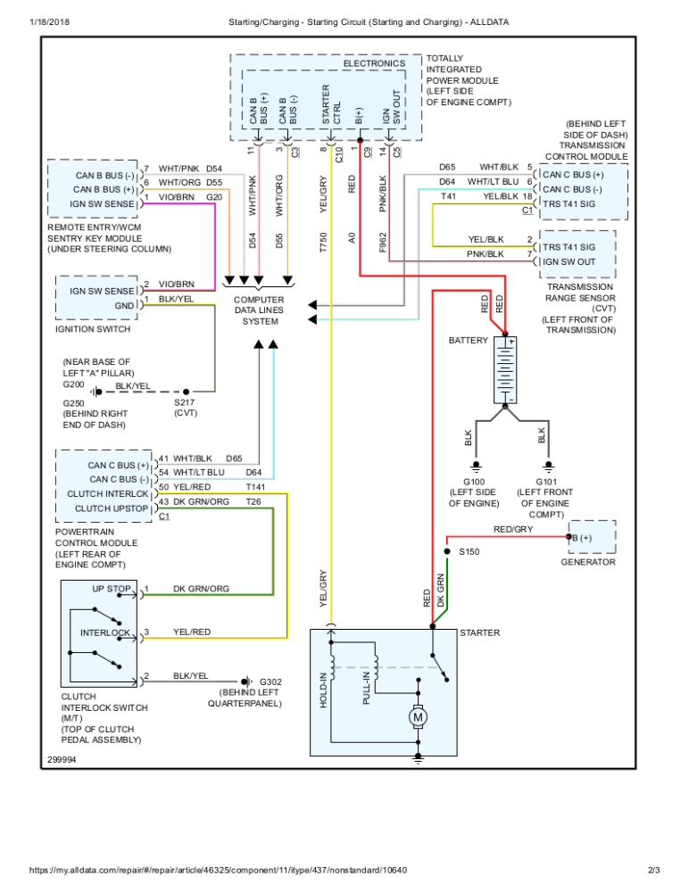
The Intrusive Transceiver Module is located in the dome light fixture. I highly doubt this would cause an issue, but no power to the fuse could mean other modules are not being powered up. Please verify.
DESCRIPTION
The Vehicle Theft Security System (VTSS) is an available feature on this vehicle. The VTSS is comprised of two primary subsystems: the optional Vehicle Theft Alarm (VTA) and the standard Sentry Key Immobilizer System (SKIS). The VTA is an active system that provides visual and audible responses as deterrents to and warnings of unauthorized vehicle tampering. The SKIS is a passive system that effectively immobilizes the vehicle against unauthorized operation. Following are paragraphs which describe these subsystems of the VTSS.
Certain functions and features of the VTSS rely upon resources shared with or controlled by other electronic modules in the vehicle over the Controller Area Network (CAN) data bus. Other modules that may affect VTSS operation are:
- Electro Mechanical Instrument Cluster - The Electro Mechanical Instrument Cluster (EMIC) (also known as the Cab Compartment Node/CCN) provides door and liftgate ajar switch status. The EMIC also provides the VTA system logic and security indicator control. See: Instrument Cluster / Carrier > Components > Instrument Cluster - Description.
- Powertrain Control Module - The Powertrain Control Module (PCM) provides the SKIS engine control logic. . See: Engine Control Module > Components > Powertrain Control Module - Description
- Totally Integrated Power Module - The Totally Integrated Power Module (TIPM) is located in the engine compartment, near the battery. See: Power Distribution Module > Components > Totally Integrated Power Module (TIPM) - Description.
Except for the Sentry Key transponders, which rely upon Radio Frequency (RF) communication, hard wired circuitry connects the VTA and SKIS components to the electrical system of the vehicle. These hard wired circuits are integral to several wire harnesses, which are routed throughout the vehicle and retained by many different methods. These circuits may be connected to each other, to the vehicle electrical system and to the SKIS components through the use of a combination of soldered splices, splice block connectors, and many different types of wire harness terminal connectors and insulators. Refer to the appropriate wiring information. The wiring information includes wiring diagrams, proper wire and connector repair procedures, further details on wire harness routing and retention, as well as pin-out and location views for the various wire harness connectors, splices and grounds.
VEHICLE THEFT ALARM
The VTA is available in two different configurations for this vehicle: One configuration is designed for vehicles manufactured for sale in North America; while, the other configuration is designed for vehicles manufactured for sale in markets outside of North America, also referred to as export markets within the context of this service information. In addition, the VTA for export is available in two versions: base and premium. All vehicles equipped with VTA are also equipped with the Remote Keyless Entry (RKE) system and the Sentry Key Immobilizer System (SKIS), regardless of their market destination.
The North American and export base version of the VTA system provide perimeter vehicle protection by monitoring the vehicle doors, the ignition switch, the liftgate and, for vehicles built for certain markets where it is required equipment, the hood. If unauthorized vehicle use or tampering is detected, these systems respond by pulsing the vehicle horn as an audible deterrent and flashing certain exterior lamps as a visual deterrent.
The export premium version of the VTA system is only available in vehicles manufactured for sale in certain markets where it is required equipment. The export premium version of the VTA provides the same perimeter protection features as the base version, but adds interior vehicle intrusion protection. The export premium VTA also replaces the pulsing horn feature of the base version with an alarm siren as the audible deterrent, while retaining the flashing exterior lamps as the visual deterrent.
The VTA includes the following major components, which are described in further detail elsewhere in this service information:
- Door Ajar Switches - A door ajar switch is integral to the door latch mechanism of each front and rear door.
- Hood Ajar Switch - A hood ajar switch is located in a bracket on the inner fender within the engine compartment of vehicles built for sale in certain export markets where it is required equipment.
- Intrusion Transceiver Module - An intrusion transceiver module (ITM) is integral to the dome lamp located in the center of the headliner over the rear seating area in the passenger compartment of vehicles built for sale in certain export markets where it is required equipment.
- Liftgate Ajar Switch - A liftgate ajar switch is integral to the latch for the liftgate in the vehicle.
- Security Indicator - A security indicator is integral to the Electro Mechanical Instrument Cluster (EMIC) (also known as the Cab Compartment Node/CCN). See: Instrument Cluster / Carrier > Components > Instrument Cluster - Description.
- Siren (2) - An alarm siren is located on the outboard side of the right front fender load path beam above the wheel house splash shield of vehicles built for sale in certain export markets where it is required equipment.
SENTRY KEY IMMOBILIZER SYSTEM
The Sentry Key Immobilizer System (SKIS) is standard factory-installed equipment on this vehicle. The SKIS provides passive vehicle protection by preventing the engine from operating unless a valid electronically encoded key is detected in the ignition lock cylinder.
The SKIS includes the following major components, which are described in further detail elsewhere in this service information:
- Security Indicator - A security indicator is integral to the Electro Mechanical Instrument Cluster (EMIC) (also known as the Cab Compartment Node/CCN). See: Instrument Cluster / Carrier > Components > Instrument Cluster - Description.
- Sentry Key Remote Entry Module - The Sentry Key REmote Entry Module (SKREEM) (also known as the Wireless Control Module/WCM) is located on the right side of the steering column near the ignition lock cylinder housing and an integral molded plastic antenna ring circles the ignition lock cylinder like a halo. The SKREEM and its antenna are concealed beneath the shrouds on the steering column. See: Alarm Module, (Vehicle Antitheft) > Components > Sentry Key Immobilizer Module (SKREEM) - Description.
- Sentry Key Transponder - The Sentry Key transponder is contained within the Remote Keyless Entry (RKE) transmitter integral to the head of the ignition key. See: Alarm System Transponder > Components > Transponder Key - Description.
Confirm what it's not, and fix what it is!
Please Log in or Create an account to join the conversation.
- graywave
-
- Offline
- Elite Member
-
- Adv. Diagnostics New Hampshire
- Posts: 303
- Thank you received: 80
1. Check ALL Fuses with Key ON Engine OFF and let us know which ones do not have power.
Some more food for thought. This should help you understand the system operation a little more
MODES OF OPERATION
As input signals to the PCM change, the PCM adjusts its response to output devices. For example, the PCM must calculate a different injector pulse width and ignition timing for idle than it does for Wide Open Throttle (WOT). There are several different modes of operation that determine how the PCM responds to the various input signals.
There are two different areas of operation, OPEN LOOP and CLOSED LOOP.
During OPEN LOOP modes the PCM receives input signals and responds according to preset PCM programming. Inputs from the upstream and downstream heated oxygen sensors are not monitored during OPEN LOOP modes, except for heated oxygen sensor diagnostics (they are checked for shorted conditions at all times).
During CLOSED LOOP modes the PCM monitors the inputs from the upstream and downstream heated oxygen sensors. The upstream heated oxygen sensor input tells the PCM if the calculated injector pulse width resulted in the ideal air-fuel ratio of 14.7 to one. By monitoring the exhaust oxygen content through the upstream heated oxygen sensor, the PCM can fine tune injector pulse width. Fine tuning injector pulse width allows the PCM to achieve optimum fuel economy combined with low emissions.
For the PCM to enter CLOSED LOOP operation, the following must occur:
1. Engine coolant temperature must be over 1.6°C (35°F).
- If the coolant is over 1.6°C (35°F) the PCM will wait 38 seconds.
- If the coolant is over 10°C (50°F) the PCM will wait 15 seconds.
- If the coolant is over 75°C (167°F) the PCM will wait 3 seconds.
2. For other temperatures the PCM will interpolate the correct waiting time.
3. O2 sensor must read either greater than 0.745 volts or less than 0.29 volt.
4. The multi-port fuel injection system has the following modes of operation:
- Ignition switch ON (Zero RPM)
- Engine start-up
- Engine warm-up
- Cruise
- Idle
- Acceleration
- Deceleration
- Wide Open Throttle
- Ignition switch OFF
5. The engine start-up (crank), engine warm-up, deceleration with fuel shutoff and wide open throttle modes are OPEN LOOP modes. Under most operating conditions, the acceleration, deceleration (with A/C on), idle and cruise modes, with the engine at operating temperature are CLOSED LOOP modes.
IGNITION SWITCH ON (ZERO RPM) MODE
When the ignition switch activates the fuel injection system, the following actions occur:
- The PCM monitors the engine coolant temperature sensor and throttle position sensor input. The PCM determines basic fuel injector pulse width from this input.
- The PCM determines atmospheric air pressure from the MAP sensor input to modify injector pulse width.
When the key is in the ON position and the engine is not running (zero rpm), the Auto Shutdown (ASD) and fuel pump relays de-energize after approximately 1 second. Therefore, battery voltage is not supplied to the fuel pump, ignition coil, fuel injectors and heated oxygen sensors.
ENGINE START-UP MODE
This is an OPEN LOOP mode. If the vehicle is in park or neutral (automatic transaxles) or the clutch pedal is depressed (manual transaxles) the ignition switch energizes the starter relay when the engine is not running. The following actions occur when the starter motor is engaged:
- If the PCM receives the camshaft position sensor and crankshaft position sensor signals, it energizes the fuel pump. If the PCM does not receive both signals within approximately one second, it will not energize the fuel pump. The PCM supplies voltage to the fuel pump, fuel injectors, ignition coil, (EGR solenoid and PCV heater if equipped) and heated oxygen sensors.
- The PCM energizes the injectors (on the 69 degree falling edge) for a calculated pulse width until it determines crankshaft position from the camshaft position sensor and crankshaft position sensor signals. The PCM determines crankshaft position within 1 engine revolution.
- After determining crankshaft position, the PCM begins energizing the injectors in sequence. It adjusts injector pulse width and controls injector synchronization by turning the individual ground paths to the injectors On and Off.
- When the engine idles within ±64 RPM of its target RPM, the PCM compares current MAP sensor value with the atmospheric pressure value received during the Ignition Switch On (zero RPM) mode.
Once the fuel pump relay has been energized, the PCM determines injector pulse width based on the following:
- MAP
- Engine RPM
- Battery voltage
- Engine coolant temperature
- Inlet/Intake air temperature (IAT)
- Throttle position
- The number of engine revolutions since cranking was initiated
During Start-up the PCM maintains ignition timing at 9 degrees BTDC.
ENGINE WARM-UP MODE
This is an OPEN LOOP mode. The following inputs are received by the PCM:
- Manifold Absolute Pressure (MAP)
- Crankshaft position (engine speed)
- Engine coolant temperature
- Inlet/Intake air temperature (IAT)
- Camshaft position
- Knock sensor
- Throttle position
- A/C switch status
- Battery voltage
- Vehicle speed
- Speed control
- O2 sensors
The PCM adjusts injector pulse width and controls injector synchronization by turning the individual ground paths to the injectors On and Off.
The PCM adjusts ignition timing and engine idle speed. Engine idle speed is adjusted through the idle air control motor.
CRUISE OR IDLE MODE
When the engine is at operating temperature this is a CLOSED LOOP mode. During cruising or idle the following inputs are received by the PCM:
- Manifold absolute pressure
- Crankshaft position (engine speed)
- Inlet/Intake air temperature
- Engine coolant temperature
- Camshaft position
- Knock sensor
- Throttle position
- Exhaust gas oxygen content (O2 sensors)
- A/C switch status
- Battery voltage
- Vehicle speed
The PCM adjusts injector pulse width and controls injector synchronization by turning the individual ground paths to the injectors On and Off.
The PCM adjusts engine idle speed and ignition timing. The PCM adjusts the air/fuel ratio according to the oxygen content in the exhaust gas (measured by the upstream and downstream heated oxygen sensor).
The PCM monitors for engine misfire. During active misfire and depending on the severity, the PCM either continuously illuminates or flashes the malfunction indicator lamp (Check Engine light on instrument panel). Also, the PCM stores an engine misfire DTC in memory, if 2nd trip with fault.
The PCM performs several diagnostic routines. They include:
- Oxygen sensor monitor
- Downstream heated oxygen sensor diagnostics during open loop operation (except for shorted)
- Fuel system monitor
- EGR monitor (if equipped)
- Purge system monitor
- Catalyst efficiency monitor
- All inputs monitored for proper voltage range, rationality.
- All monitored components.
The PCM compares the upstream and downstream heated oxygen sensor inputs to measure catalytic converter efficiency. If the catalyst efficiency drops below the minimum acceptable percentage, the PCM stores a diagnostic trouble code in memory, after 2 trips.
During certain idle conditions, the PCM may enter a variable idle speed strategy. During variable idle speed strategy the PCM adjusts engine speed based on the following inputs.
- A/C status
- Battery voltage
- Battery temperature or Calculated Battery Temperature
- Engine coolant temperature
- Engine run time
- Inlet/Intake air temperature
- Vehicle mileage
ACCELERATION MODE
This is a CLOSED LOOP mode. The PCM recognizes an abrupt increase in Throttle Position sensor output voltage or MAP sensor output voltage as a demand for increased engine output and vehicle acceleration. The PCM increases injector pulse width in response to increased fuel demand.
- Wide Open Throttle-open loop
DECELERATION MODE
This is a CLOSED LOOP mode. During deceleration the following inputs are received by the PCM:
- A/C status
- Battery voltage
- Inlet/Intake air temperature
- Engine coolant temperature
- Crankshaft position (engine speed)
- Exhaust gas oxygen content (upstream heated oxygen sensor)
- Knock sensor
- Manifold absolute pressure
- Throttle position sensor
The PCM may receive a closed throttle input from the APPS when it senses an abrupt decrease in manifold pressure. This indicates a hard deceleration (Open Loop). In response, the PCM may momentarily turn off the injectors. This helps improve fuel economy, emissions and engine braking.
WIDE-OPEN-THROTTLE MODE
This is an OPEN LOOP mode. During wide-open-throttle operation, the following inputs are used by the PCM:
- Inlet/Intake air temperature
- Engine coolant temperature
- Engine speed
- Knock sensor
- Manifold absolute pressure
- Throttle position
When the PCM senses a wide-open-throttle condition through the APPS it de-energizes the A/C compressor clutch relay. This disables the air conditioning system and disables EGR (if equipped).
The PCM adjusts injector pulse width to supply a predetermined amount of additional fuel, based on MAP and RPM.
IGNITION SWITCH OFF MODE
When the operator turns the ignition switch to the OFF position, the following occurs:
- All outputs are turned off, unless 02 Heater Monitor test is being run.
- No inputs are monitored except for the heated oxygen sensors. The PCM monitors the heating elements in the oxygen sensors and then shuts down.
RELATED INFORMATION
Description and Operation
Components
Diagrams
Electrical (OE)
Parts and Labor
Computers and Control Systems
Technical Service Bulletins
All Technical Service Bulletins
By Symptom
Customer Interest Bulletins
Recalls and Campaigns
Testing and Inspection
Component Tests and General Diagnostics
Initial Inspection and Diagnostic Overview
Mode 6 Data
Monitors, Trips, Drive Cycles and Readiness Codes
Pinout Values and Diagnostic Parameters
Reading and Clearing Diagnostic Trouble Codes
Scan Tool Testing and Procedures
Symptom Related Diagnostic Procedures
Tools and Equipment
Electrical / Mechanical Repair
Confirm what it's not, and fix what it is!
Please Log in or Create an account to join the conversation.
- Hydo
-
Topic Author
- Offline
- New Member
-
- Ehh
- Posts: 7
- Thank you received: 0
Please Log in or Create an account to join the conversation.
- Hydo
-
Topic Author
- Offline
- New Member
-
- Ehh
- Posts: 7
- Thank you received: 0
The obd scanner isnt reading any data,I also found a a power wire from battery to TIPM rubbed thru near metal.
I also unplugged plug from igntion switch,got power from the red wire.unplugged ecu couldnt find power there.
Please Log in or Create an account to join the conversation.