98 Blazer Help Understanding Wiper Circuit
- rockp2
-
 Topic Author
- Offline
- Elite Member
-

- Posts: 167
- Thank you received: 40
I have questions concerning the resistors in the multi-function switch. I had come to understand that if there is only one resistor in the path, there would be no voltage drop due to the resistor? Since the connector was unplugged from the motor, there was no other resistor in the direct path. What am I missing or not understanding? The TSM states I should get battery power from those three wires. It does not state anything to indicate there would be differences in any of the wire voltage due to the position of the switch when measuring the power.
Please help me understand. Thanks much!
Please Log in or Create an account to join the conversation.
- castironman
-

- Offline
- Junior Member
-

- Posts: 25
- Thank you received: 3
Please Log in or Create an account to join the conversation.
- rockp2
-
Topic Author
- Offline
- Elite Member
-
- Posts: 167
- Thank you received: 40
Please Log in or Create an account to join the conversation.
- castironman
-
- Offline
- Junior Member
-
- Posts: 25
- Thank you received: 3
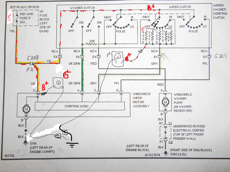
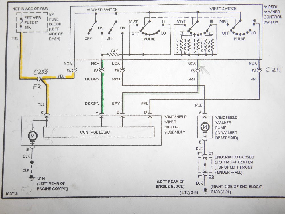
Okay, let's try this: I imagine you are using a digital multimeter with at least 10 mega ohm input impedance. If you disconnect the windshield motor assembly, ignition key in acc or run, move the speed selector to the 680K you should measure B+ voltage at that point or point E at the connector as well as C on the same connector, as long as E5 on connector C211 is not corroded. This happens because the high impedance in your meter you did not allowed current to pass, but if you use an analog meter, then you will see the voltage drop. Thank you. I will see if I can find a picture of your control switch.
Please Log in or Create an account to join the conversation.
- castironman
-
- Offline
- Junior Member
-
- Posts: 25
- Thank you received: 3
www.amazon.com/Dorman-Wiper-Pulse-Board-88136/dp/B0002JMU3E
Please Log in or Create an account to join the conversation.
- Noah
-

- Offline
- Moderator
-

- Posts: 5028
- Thank you received: 1119
I understand where you're coming from, that with the wiper motor disconnected, there should be 12v on the grey wire regardless of switch position because no current flow=no voltage drop.
But, isn't the yellow power wire in the same connector?
Meaning, with the connector disconnected, there would be no power going to the switch. So I don't see how you are measuring anything on the grey wire with the motor disconnected, unless, your are maybe measuring on the motor side of the connector and not the switch side?
Please Log in or Create an account to join the conversation.
- castironman
-
- Offline
- Junior Member
-
- Posts: 25
- Thank you received: 3
Please Log in or Create an account to join the conversation.
- Noah
-
- Offline
- Moderator
-
- Posts: 5028
- Thank you received: 1119
Please Log in or Create an account to join the conversation.
- rockp2
-
Topic Author
- Offline
- Elite Member
-
- Posts: 167
- Thank you received: 40
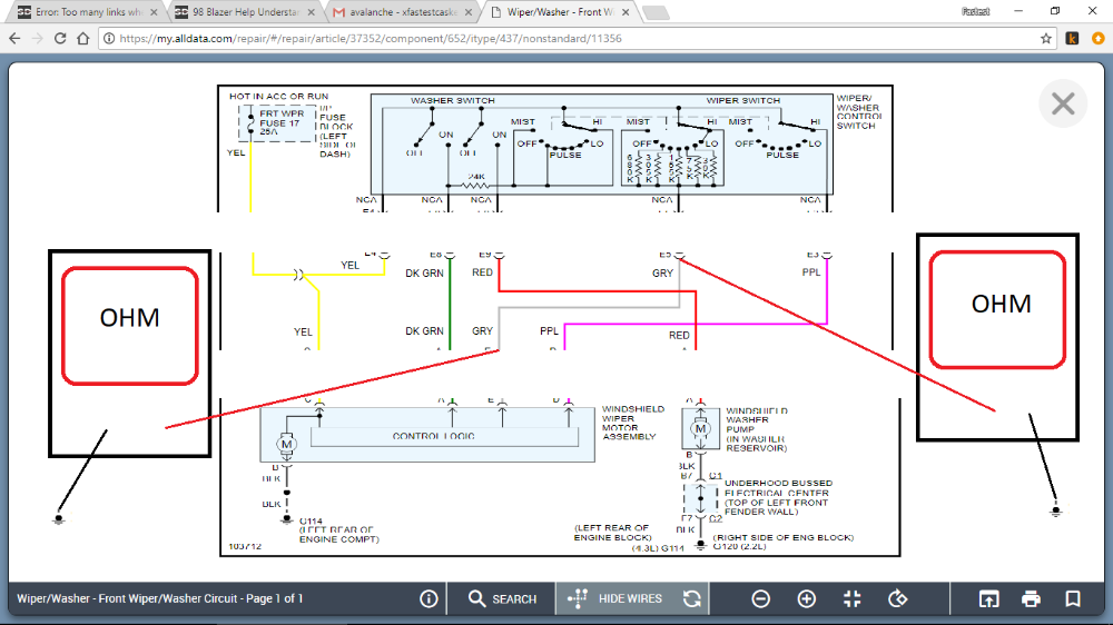
Castironman, I believe you and I are saying the same thing, that with C211 disconnected (KOEO) I should not get a voltage drop (measuring at C211) on the grey wire regardless of the PULSE position on the multi-function switch. This is what I initially wanted to verify. Just to note, the multifunction switch controls the turn signals, wipers, hazards, washer pump and cruise control.
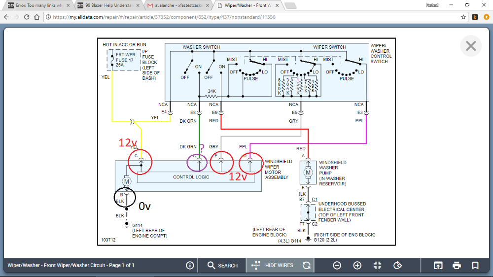
Noah, C203 was left connected and is inside the cabin behind the knee bolster. So constant B+ is supplied (KOEO) through the YEL wire. When putting wiper switch in PULSE mode, there is also supposed to be B+ on the GRY and DK GRN wires also (once again measuring at C211 disconnected (harness side)). However, on the GRY wire I am getting a voltage drop as high as .75 volt when compared to YEL wire.
Because this was driving me a little batty, and due to my level of understanding circuitry (novice at best), I went online and bought a little electronics kit that included, among other things; a breadboard, various resistors and wires to work on the breadboard. I created a circuit similar to the multi-function switch wiper circuit. I was curious to know if there would be resistance due to the resistors sharing (but not in series) the GRY wire. When I set the circuit up I found there was no resistance when measuring in the various positions. Not until I added another resistor (acting as resistor in the control logic of the wiper motor) in series to one of the other resistors did the ohms measure up.
If I am correct, this confirms to me that regardless of the PULSE position of the switch (not counting the OFF position), at C211 (disconnected, KOEO, harness side) I should be measuring the same voltage as I do on the YEL wire. This leads me to believe that somewhere in the GRY wire there is a resistance (corrosion, worn covering touching one of the other wires, etc) that is acting as an unwanted resistor in series with the resistor at each position PULSE position the multi-function switch.
My thinking is that replacing the circuit board in the wiper motor would not solve the problem because I would still not be supplying the correct voltage the motor logic is expecting through the GRY wire. Thoughts?
And thank you very much for bearing with me (did I use the word resistor enough?
") ). I really want to understand circuitry and what is right and what is wrong before I replace parts.
). I really want to understand circuitry and what is right and what is wrong before I replace parts. Please Log in or Create an account to join the conversation.
- Noah
-
- Offline
- Moderator
-
- Posts: 5028
- Thank you received: 1119
I've been waiting for an update
")
There's no reason I can see for voltage to drop on that wire, unless like you theorized, there is some kind of resistive short to ground before your test point. Or maybe (long shot here) a cheap multimeter with not enough internal resistance, but I've never had a meter to that significantly dropped voltage on a 12v circuit...
You could disconnect c211 and the wiper motor, then check the grey wire with an ohm meter to see if there is any continuity to ground.
Thinking of the symptoms, you say that the wipers only work at 50-70% speed on high.
High is a direct circuit to full battery power. I would check power at the purple wire, and the ground at the motor with everything connected and wipers running.
Please Log in or Create an account to join the conversation.
- rockp2
-
Topic Author
- Offline
- Elite Member
-
- Posts: 167
- Thank you received: 40
Noah wrote: Did you get any where with this one?
I've been waiting for an update
Hi Noah, haven't been back on the truck since my last post a couple days ago. I really appreciate your input and am going to run back through tests with the wiper motor running again to see what that turns up. Then I think I'm going to go ahead and disconnect C203 &C211 and see if I get any continuity between separate wires and also ground for each one. If I get any, then I'll at least have it nailed down to somewhere in the harness. Finding the short to power/ground/neighbor will be a completely different "pleasant" experience.
Also, I'm using a really good Fluke 115 True RMS meter. Thanks! Please Log in or Create an account to join the conversation.
- rockp2
-
Topic Author
- Offline
- Elite Member
-
- Posts: 167
- Thank you received: 40
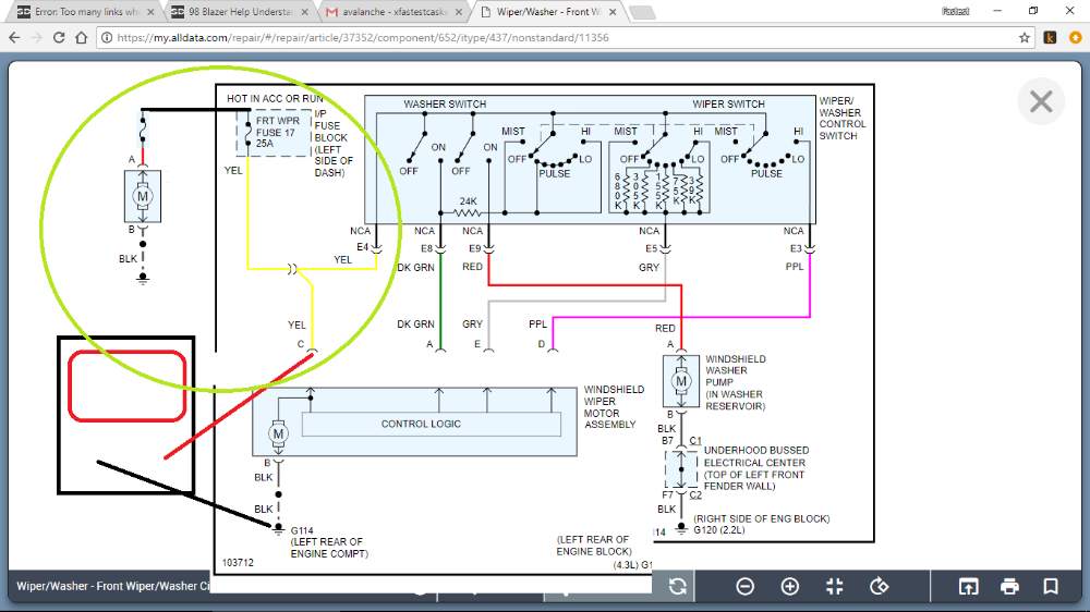
Then I pulled IP fuze #17. Measured YEL again and got what I believe I should. No blip of tone, no light and the display was blank. I believe this means I do have an issue, but it's obviously further upstream from IP fuze #17. Could someone confirm that I shouldn't be getting that quick ground tone (and green light) and then the 00.18v on the PPIV display on the YEL wire. Please confirm that I should get no reading/tone/light at all? Thanks much.
Please Log in or Create an account to join the conversation.
- rockp2
-
Topic Author
- Offline
- Elite Member
-
- Posts: 167
- Thank you received: 40
Please Log in or Create an account to join the conversation.
- rockp2
-
Topic Author
- Offline
- Elite Member
-
- Posts: 167
- Thank you received: 40
Please Log in or Create an account to join the conversation.
- Noah
-
- Offline
- Moderator
-
- Posts: 5028
- Thank you received: 1119
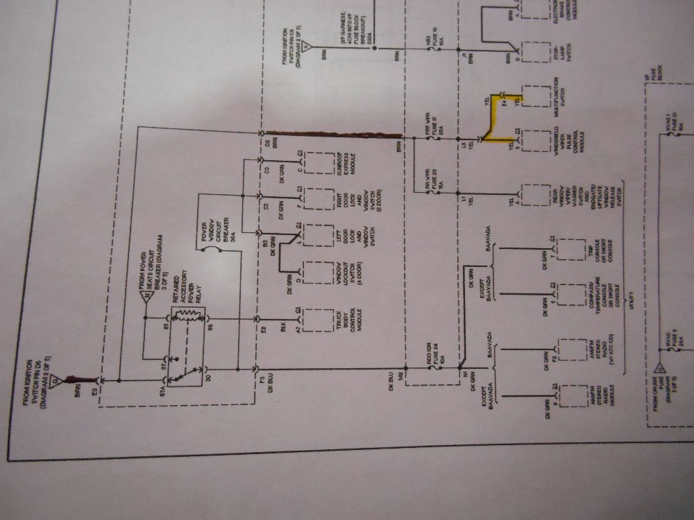
That diagram is real small on my phone, but the circuit also includes that relay which is shown to provide a path to whatever those other components are (sorry, can't make them out) while in the rest position.
That's probably why taking the fuse (and the relay) out of the circuit shows open circuit voltage.
I really like my power probe 4, you can hammer through a lot of problems with one. But you can also end up chasing your tail.
Please Log in or Create an account to join the conversation.
- rockp2
-
Topic Author
- Offline
- Elite Member
-
- Posts: 167
- Thank you received: 40
Then last night I was playing with my new Maxisys (thank you to those that helped me choose the tool) and found a BCM DTC stored in history. On my truck this does not set any MIL lights so I didn't even know it was there. The DTC is B1477 (Retained Accessory Power Circuit Low). Referencing the former post where I described what I thought to be a weird reading on my PPIV when measuring the YEL wire, I am now wondering if there might be something to that after all?
My thought process is that since the PPIV would have that half second ground blip on the YEL wire, maybe there is some initial noise or junk or something that is the reason the wipers wouldn't immediately start in the pulse mode until the "2nd" time for them to wipe. Since the YEL wire does (upstream) split to include the RAP, that there may be some connection. That maybe the RAP is pulling down some voltage in the YEL wire that should be going to the wiper motor? Not a whole lot to be really perceivable, but just enough.
I've already done some reading on the B1477 and when I get a chance to dig back under the dash I will look into the troubleshooting on it.
Any thoughts are welcome and I hope i have not bored everyone too much.
Thank you. Please Log in or Create an account to join the conversation.
- Noah
-
- Offline
- Moderator
-
- Posts: 5028
- Thank you received: 1119
When you touch on the yellow wire with the power probe and the key off, it's acting like an Ohm meter. So it's finding a path to ground through the rest of the circuits from in front of the fuse. That's why you are getting the momentary green LED blip.
I still don't have a good answer concerning the voltage readings you observed on the grey wire with the motor disconnected running the wiper selector through the modes. I would Ohm check that wire to ground on both ends with the motor and switch disconnected. A check on one end would likely be sufficient, but what's another couple minutes on your own truck? The only acceptable reading here is OL Mohms. (If your fluke doesn't have auto ranging, make sure it's set at Mega Ohms).
Next, I would set it to high with everything connected (and running) and check voltage at the wiper motor connector. At the purple, grey and yellow I expect battery voltage, the black wire ground voltage, and something else on the green wire. (Lol, sorry, not taking a shot at that. Somebody want to do the math? 12v, 24 kohm resistor?)
After that, the only real checks left in my eyes are for mechanical binding in the wiper transmission or arms, then time for a new motor. I suppose you could measure the current draw of the motor, but I couldn't tell you what to expect from a good or a bad one.
I hope this helps you out.
Sorry for the delay in getting back to you.
Please Log in or Create an account to join the conversation.
- chief eaglebear
-
- Offline
- Platinum Member
-

- Posts: 340
- Thank you received: 70
Please Log in or Create an account to join the conversation.
- chief eaglebear
-
- Offline
- Platinum Member
-
- Posts: 340
- Thank you received: 70
Please Log in or Create an account to join the conversation.
- rockp2
-
Topic Author
- Offline
- Elite Member
-
- Posts: 167
- Thank you received: 40
Please Log in or Create an account to join the conversation.