p01860 TCC PWM code. P01Gen3 ECU 4L60E transmission
- lsstag
-
 Topic Author
- Offline
- New Member
-

- Posts: 9
- Thank you received: 0
First post.
I have a custom car. Here are the details
6.0l LQ9 LS3 engine brand new
4L60E transmission rebuilt all new components
Reconditioned ECU
On first start up it is throwing a P01860 TCC PWM Solenoid Circuit Electrical code.
I have checked volatge to the E pin on the 13pin electrical connector at the transmission it reads 12 Volts. I have continuity through the solenoid. When I unplug the ECU connector I have 12 volts at pin2 on the red connector. With the ecu connector plugged back in I have no voltage. Is this circuit normally open or closed. I know it gets pulsed but with everything connected sould I be seeing 12 volts at the ECU with the key on engine off.
Any direction would be helpful
Thanks .
Please Log in or Create an account to join the conversation.
- Tyler
-

- Offline
- Moderator
-

- Full time HACK since 2012
- Posts: 6129
- Thank you received: 1544
You didn't specify the donor vehicle for your custom car, so I took a guess at a 2003 Silverado SS. Service info for P1860 is specific about code set criteria:
To answer your question about the circuit, you'd need a scan tool to see what the TCC solenoid command is while the fault sets. My guess is it's gonna be condition 2, but it's worth checking the scan data anyway.Condition 1 The PCM commands the solenoid ON, 90 percent, and the voltage feedback remains high, B+.
Condition 2 The PCM commands the solenoid OFF, 0 percent, and the voltage feedback remains low, 0 volt.
There's some steps in the P1860 flow chart that I think are worth following:
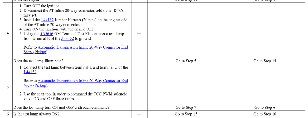
You probably don't have the special J-tools, and that's fine. All we really want to know is:
1.) Does pin E light a test light to ground? I know you already checked voltage, but we're looking for a loaded circuit test.
2.) What does a test light between pin E and U do during a bidirectional test?
Let us know what you find!
Please Log in or Create an account to join the conversation.
- lsstag
-
Topic Author
- Offline
- New Member
-
- Posts: 9
- Thank you received: 0
I will go through the tests and let you know.
How do I do the bidirectional test?
Thanks again
Please Log in or Create an account to join the conversation.
- Tyler
-
- Offline
- Moderator
-
- Full time HACK since 2012
- Posts: 6129
- Thank you received: 1544
How do I do the bidirectional test?
You'll need a scan tool with bidirectional capability. Which scan tool do you buy? That's going to depend a lot on your needs and your budget.
As always, I'm a big fan of the TopDon TopScan. It'll allow you to look at the TCC command %, and it'll very likely have the bidirectional test. Affordable and readily available.
www.amazon.com/TOPDON-Bluetooth-Diagnost...ional/dp/B0C3QQYQ1B/
Please Log in or Create an account to join the conversation.
- lsstag
-
Topic Author
- Offline
- New Member
-
- Posts: 9
- Thank you received: 0
I took a look and my scan tool does not do bidirectional, but it looks like I can do it in HPTuners. What I have done so far was 1. disconnted the 13pin connector and used a test light (not LED type) between pin E and ground and I had light. 2. while the connector was still umplugged I put my test light between pins E and pin U on the harness side of the connector and cycled the PWN Solenoid from iside HPTuners. The test light stayed on all the time. 3. I became a parts changer and swapped out the PCM for another that I had and still the same code. 4. With the connector still disconected I did an OHM test beteen the two pins E and U on the transmission side to check the OHMS of the solenoid which read 10.2 OHMS. I am going to do a little more research today on the HPTuners side to make sure that what I was doing was indeed a bidirectional test. Thanks for all the advice and help.
Please Log in or Create an account to join the conversation.
- Tyler
-
- Offline
- Moderator
-
- Full time HACK since 2012
- Posts: 6129
- Thank you received: 1544
Well damn, that sucks! Kinda what I was afraid of.2. while the connector was still umplugged I put my test light between pins E and pin U on the harness side of the connector and cycled the PWN Solenoid from iside HPTuners. The test light stayed on all the time.
Don't sweat it. If you follow the flow chart in SI for 'light stays on', it ends in PCM replacement.3. I became a parts changer and swapped out the PCM for another that I had and still the same code.
Service info specifies 10-15 ohms for the TCC PWM solenoid, so I'd call that good.4. With the connector still disconected I did an OHM test beteen the two pins E and U on the transmission side to check the OHMS of the solenoid which read 10.2 OHMS
If you were doing it with the engine running the first time, try key on engine off. Otherwise, I bet you were probably doing it right.I am going to do a little more research today on the HPTuners side to make sure that what I was doing was indeed a bidirectional test. Thanks for all the advice and help.
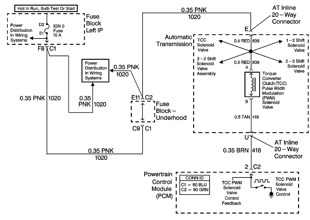
At this point I have to question the harness. Circuit #418 for the TCC PWM control goes from pin U at the transmission to pin #2 of connector 2. It sucks, but it may be time to ohm between pin U and pin #2 of C2. We want to make sure that circuit #418 is going to the correct pin at the PCM.
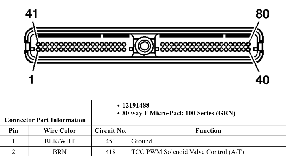
You mentioned in your first post that you were testing at the red connector. The wiring diagram indicates that C2 is green. Some quick Googling shows that has to do with the model year of the donor powertrain. Does that sound right?
Please Log in or Create an account to join the conversation.
- lsstag
-
Topic Author
- Offline
- New Member
-
- Posts: 9
- Thank you received: 0
Thanks for the response. Here we go...
The harness is a completly custom hand built harness I did. The power to the transmission has its own relay and fuse and is seperated from all other systems (actually each system coil, injectors , sensors are all on their own fuses and designated banks) using 18 AWG wire throught out. I do like your thoughts of doing an ohms test between the two pins just to see what I get, that is very easy to do. There was no doner car. The engine is a GM create engine and the transmission came directly from a transmission shop. Everything is based on a '99-'02 P01 Gen3 PCM which has the blue and red connectors.
Dont even ask what car this is all in. It will make your head hurt......
Here is the schematic for it that I have been using for reference..
www.lt1swap.com/pictures/99_02_schematic...%20Stop%20Switch.gif
Thanks again for taking time for this
Mike
Please Log in or Create an account to join the conversation.
- Tyler
-
- Offline
- Moderator
-
- Full time HACK since 2012
- Posts: 6129
- Thank you received: 1544
Gotcha, thank you for the clarification! I actually made my way onto lt1swap.com the other night while looking for info about the PCM connectors.The harness is a completly custom hand built harness I did. The power to the transmission has its own relay and fuse and is seperated from all other systems (actually each system coil, injectors , sensors are all on their own fuses and designated banks) using 18 AWG wire throught out. I do like your thoughts of doing an ohms test between the two pins just to see what I get, that is very easy to do. There was no doner car. The engine is a GM create engine and the transmission came directly from a transmission shop. Everything is based on a '99-'02 P01 Gen3 PCM which has the blue and red connectors.
Let me know what you find with the continuity test.
Please Log in or Create an account to join the conversation.
- lsstag
-
Topic Author
- Offline
- New Member
-
- Posts: 9
- Thank you received: 0
I continuity is good. I did get the topscan and will play with that tomorrow. I dont think HPTuners actually did the bi-directional test like you mentioned.
I am going to redo it with Topscan and see wha the result is. I will let you know how it goes. If we dont talk have a great New Years...
Please Log in or Create an account to join the conversation.
- lsstag
-
Topic Author
- Offline
- New Member
-
- Posts: 9
- Thank you received: 0
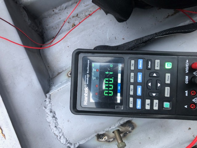
Attachment not found
I did more testing and this time I took screenshots. The first is the resistenance between the trans connector and pin2 of the PCM . The second was with the scantool you mentioned above and running the bi-directional test. Everything we have done all points to a bad PCM. I also manually activated the solenoid and I could hear it cliniing on and off as I pulsed it.
I am out of ideas here now other then PCM.
I would like to know the theroy and parameters that all go with how the PCM decides when to turn on and off the solenoid if you have that.
Thanks again for the time
Mike
Please Log in or Create an account to join the conversation.
- Tyler
-
- Offline
- Moderator
-
- Full time HACK since 2012
- Posts: 6129
- Thank you received: 1544
The second was with the scantool you mentioned above and running the bi-directional test. Everything we have done all points to a bad PCM
To be clear, you're still not seeing the test light flashing off and on while doing the bidirectional test? Isn't that frustrating...
You're absolutely certain that circuit #418 is going to the correct pin on C2? Is the circuit #418 pin fully clipped into the C2 connector? The pin isn't spread open? I don't mean to sound like I'm questioning your or your work. I'm just running out of ideas.
The only other thing I can think of is if the PCM (or its programming) is incorrect for the application. As in, the PCM is looking for a 4L80E but you're running a 4L60E. Whether that's a hardware issue or software, I'm not certain. That may even be configurable in HPTuners? I honestly don't know enough about this PCM to say.
I'll provide you with what I have. From the P1860 flow chart:I would like to know the theroy and parameters that all go with how the PCM decides when to turn on and off the solenoid if you have that.
From the transmission electronic component description:The torque converter clutch pulse width modulation (TCC PWM) solenoid valve controls fluid acting on the converter clutch valve, which then controls TCC apply and release. The TCC PWM solenoid valve attaches to the control valve body within the transmission. Ignition voltage goes directly to the TCC PWM solenoid valve. The powertrain control modulator (PCM) controls the TCC PWM solenoid valve by providing a ground path on CKT 418. The current flows through the TCC PWM solenoid valve coil according to the duty cycle (percentage of ON time). The TCC PWM solenoid valve provides a smooth engagement of the torque converter clutch by operating on a duty cycle percent of ON time.If the PCM detects a continuous open or short in the TCC PWM solenoid valve circuit or the TCC PWM solenoid valve, then DTC P1860 sets.
Important: TCC PWM solenoid valve resistance should be 10–11 ohms when measured at 20°C (68°F), and 13–15 ohms when measured at 100°C (212°F).The torque converter clutch PWM solenoid valve controls the fluid acting on the converter clutch valve, which then controls the TCC apply and release. This solenoid is attached to the control valve body assembly within the transmission. The TCC PWM solenoid valve provides smooth engagement of the torque converter clutch by operating on a negative duty cycle a variable percent of ON time.If a fault is detected in the TCC PWM circuit, code P1860 will set.
Finding this last bit was kinda tough, but probably answers your question better than the rest:
Torque Converter Clutch PWM Solenoid and Regulator Apply and Isolator ValveAFL fluid is routed to the TCC PWM solenoid valve, in Park the PCM has the duty cycle turned OFF. This prevents AFL fluid from entering the converter clutch signal fluid circuit. Regulated line pressure is routed to the regulator apply valve, which is open with CC signal circuit empty, and blocks line pressure from entering the regulated apply circuit. Any fluid in the regulated apply circuit will exhaust at the regulated apply valve.
Please Log in or Create an account to join the conversation.
- lsstag
-
Topic Author
- Offline
- New Member
-
- Posts: 9
- Thank you received: 0
Yes it was frustrating. No Worries on asking about my work,, I have been doing the samething more than once. Good point on the PCM programming, I was also starting to look that way and do a deeper look into both the PCM and the transmission. Thanks for the information, I like to know not only the how things work but also the why it works and what makes it work as well as the theory behind it all. When I find the root cause I will post it here for everyone. Thanks again for your time and have a great New Years
Mike
Please Log in or Create an account to join the conversation.
- Tyler
-
- Offline
- Moderator
-
- Full time HACK since 2012
- Posts: 6129
- Thank you received: 1544
Thinking along those lines, I downloaded a 2000 Silverado 6.0L stock file from the HPTuners Tune Repository, just to have something to work with. I found the 'Trans Type' option under Trans -> General:Good point on the PCM programming, I was also starting to look that way and do a deeper look into both the PCM and the transmission.
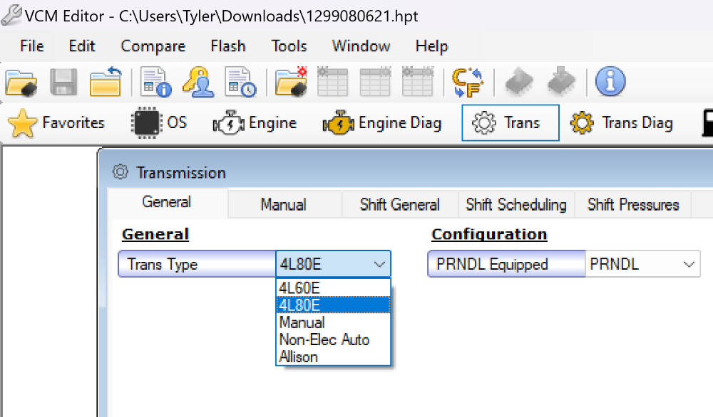
I don't know how comfy you are with VCM Editor? But I'd be interested to know which option is currently selected.
Please Log in or Create an account to join the conversation.
- lsstag
-
Topic Author
- Offline
- New Member
-
- Posts: 9
- Thank you received: 0
That was a good thought. I had already checked that out and its set to 4L60e
Please Log in or Create an account to join the conversation.
- Tyler
-
- Offline
- Moderator
-
- Full time HACK since 2012
- Posts: 6129
- Thank you received: 1544
Have you made any progress on this one?
Please Log in or Create an account to join the conversation.
- lsstag
-
Topic Author
- Offline
- New Member
-
- Posts: 9
- Thank you received: 0
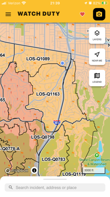
Welllll........ I was hoping to get a chance to dig into it more this weekend. but ran into a small problem as the pictures will show. Its going to be bit until things get cleaned up and back in action. We are the blue dot in the one area graph.


Please Log in or Create an account to join the conversation.