Help us help you. By posting the year, make, model and engine near the beginning of your help request, followed by the symptoms (no start, high idle, misfire etc.) Along with any prevalent Diagnostic Trouble Codes, aka DTCs, other forum members will be able to help you get to a solution more quickly and easily!
2011 CHEVY SILVERADO INOPERTAIVE 4WD 280K MILES
- JTF010
-
 Topic Author
- Offline
- New Member
-

Less
More
- Posts: 13
- Thank you received: 1
1 year 3 months ago #74279
by JTF010
2011 CHEVY SILVERADO INOPERTAIVE 4WD 280K MILES was created by JTF010
DTC C0396-05 INCREMENTAL SENSOR SHORT TO BATTERY OR OPEN (INCREMENTAL ENCODER IMPULSE AND DIRECTION SIGNAL, VOLTAGE ENCODER SIGNAL CIRCUIT LESS THEN .3V OR GREATER THAN 2.6V) TRANSFER CASE CODE MP 3023/3024
CUSTOMER STATES REPLACED TRANSFER CASE MOTOR, POSITION SENSOR, FUSE BOX, TRANSFER CASE CONTROL MODULE, FRONT DIFF ACTUATOR
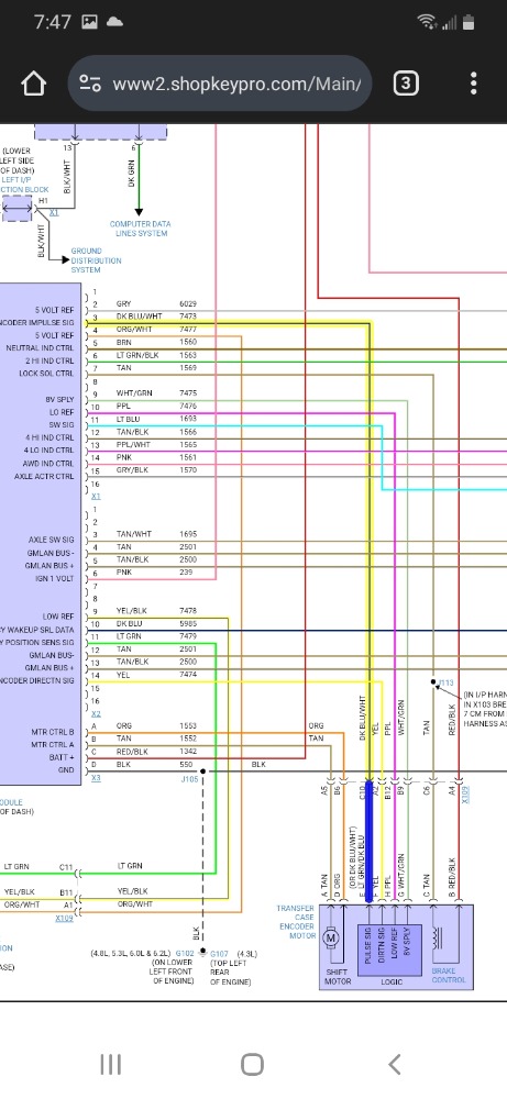
WITH SCAN TOOL YOU CAN SEE VOLTAGE FROIM THE MODULE AND THROUGH THE SWITCH, INDICATORS WILL NOT LIGHT UP OR TRY TO CHANGE WHEN TURNED, TRANSFER CASE AND DIFF ACTUATOR WORK WHEN COMMANDED WITH SCAN TOOL OR AT LEAST ENGAGING. FOLLOWED PRODEMAND TESTING PRECEDURE FOR VOLTAGE TESTING THE CIRCUITS AND FOUND ALL WAS WITHIN SPEC. TESTED CIRCUITS FOR RESISTANCE THROUGH THE TRANSFER CASE MOTOR CONNECTOR UP THE X1 CONNECTOR WIRES, ALL WIRES WERE OUT OF LIMITS BESIDES THE ONE I ORIGINALLY PROBED WITH .1 OHMS. I STILL HAVE TO TEST X2 AND X3 CONNECOTRS FOR RESISTANCE WHICH I WILL UPDATE THIS SOON. SO IT TELLS ME THAT RESISTANCE SHOULD BE GREATER THAN A CERTAIN AMOUNT OF OHMS IN THESE CIRCUITS, IF NOT THAN TEST FOR SHORTED TOGETHER WIRES, WHICH IM NOT REALLY SURE HOW TO TEST FOR THAT JUST YET. BUT IF I HAVE OUT OF LIMITS DOES THAT MEAN RESITANCE IS GREATER THAN 500 OHMS OR DOES THAT MEAN A BROKEN WIRE OR WIRES?
CUSTOMER STATES REPLACED TRANSFER CASE MOTOR, POSITION SENSOR, FUSE BOX, TRANSFER CASE CONTROL MODULE, FRONT DIFF ACTUATOR
WITH SCAN TOOL YOU CAN SEE VOLTAGE FROIM THE MODULE AND THROUGH THE SWITCH, INDICATORS WILL NOT LIGHT UP OR TRY TO CHANGE WHEN TURNED, TRANSFER CASE AND DIFF ACTUATOR WORK WHEN COMMANDED WITH SCAN TOOL OR AT LEAST ENGAGING. FOLLOWED PRODEMAND TESTING PRECEDURE FOR VOLTAGE TESTING THE CIRCUITS AND FOUND ALL WAS WITHIN SPEC. TESTED CIRCUITS FOR RESISTANCE THROUGH THE TRANSFER CASE MOTOR CONNECTOR UP THE X1 CONNECTOR WIRES, ALL WIRES WERE OUT OF LIMITS BESIDES THE ONE I ORIGINALLY PROBED WITH .1 OHMS. I STILL HAVE TO TEST X2 AND X3 CONNECOTRS FOR RESISTANCE WHICH I WILL UPDATE THIS SOON. SO IT TELLS ME THAT RESISTANCE SHOULD BE GREATER THAN A CERTAIN AMOUNT OF OHMS IN THESE CIRCUITS, IF NOT THAN TEST FOR SHORTED TOGETHER WIRES, WHICH IM NOT REALLY SURE HOW TO TEST FOR THAT JUST YET. BUT IF I HAVE OUT OF LIMITS DOES THAT MEAN RESITANCE IS GREATER THAN 500 OHMS OR DOES THAT MEAN A BROKEN WIRE OR WIRES?
Please Log in or Create an account to join the conversation.
- Noah
-

- Offline
- Moderator
-

- Give code definitions with numbers!
Less
More
- Posts: 5005
- Thank you received: 1116
1 year 3 months ago #74320
by Noah
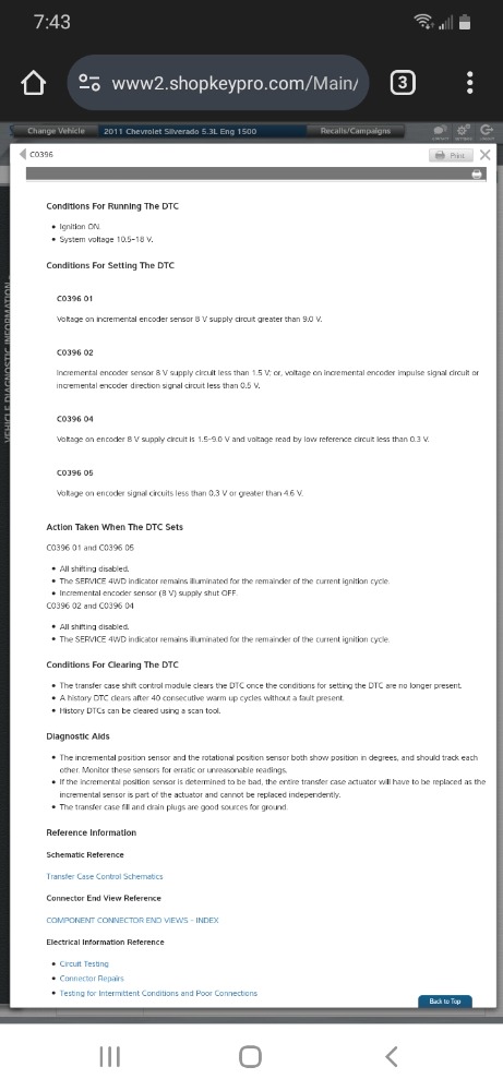
This is really good information, apparently when this code sets the 8v reference voltage for the position sensors is turned off. So for testing purposes, the code will need to be cleared. Depending on how quickly the code sets, it could make testing difficult.
Ideally, I would check the voltage at the sensor and again at the control module.
According to service info, the voltage should vary depending on position between 0.7v and 4.3v.
"Ground cannot be checked with a 10mm socket"
Replied by Noah on topic 2011 CHEVY SILVERADO INOPERTAIVE 4WD 280K MILES
This is really good information, apparently when this code sets the 8v reference voltage for the position sensors is turned off. So for testing purposes, the code will need to be cleared. Depending on how quickly the code sets, it could make testing difficult.
Ideally, I would check the voltage at the sensor and again at the control module.
According to service info, the voltage should vary depending on position between 0.7v and 4.3v.
"Ground cannot be checked with a 10mm socket"
Please Log in or Create an account to join the conversation.
- JTF010
-
Topic Author
- Offline
- New Member
-
Less
More
- Posts: 13
- Thank you received: 1
1 year 3 months ago #74330
by JTF010
Replied by JTF010 on topic 2011 CHEVY SILVERADO INOPERTAIVE 4WD 280K MILES
THANK YOU FOR YOUR FEEDBACK. I TESTED THAT WIRE ON BOTH SIDES AND FROM THE MODULE I GOT 2MV AND THE ACTUATOR SIDE I HAD 100MV TO 10MV AND I WAS USING SCAN TOOL TO COMMAND THE ACTUATOR. I THINK THEY MAY BE AN OPEN WIRE IN THE HARNESS BUT ITS HARD TO ACCESS
Please Log in or Create an account to join the conversation.
Time to create page: 0.319 seconds