Help us help you. By posting the year, make, model and engine near the beginning of your help request, followed by the symptoms (no start, high idle, misfire etc.) Along with any prevalent Diagnostic Trouble Codes, aka DTCs, other forum members will be able to help you get to a solution more quickly and easily!
Please help me interpret these waveforms for a misfire.
- All Okay Auto
-
 Topic Author
- Offline
- New Member
-

Less
More
- Posts: 12
- Thank you received: 0
1 year 3 months ago #73776
by All Okay Auto
Please help me interpret these waveforms for a misfire. was created by All Okay Auto
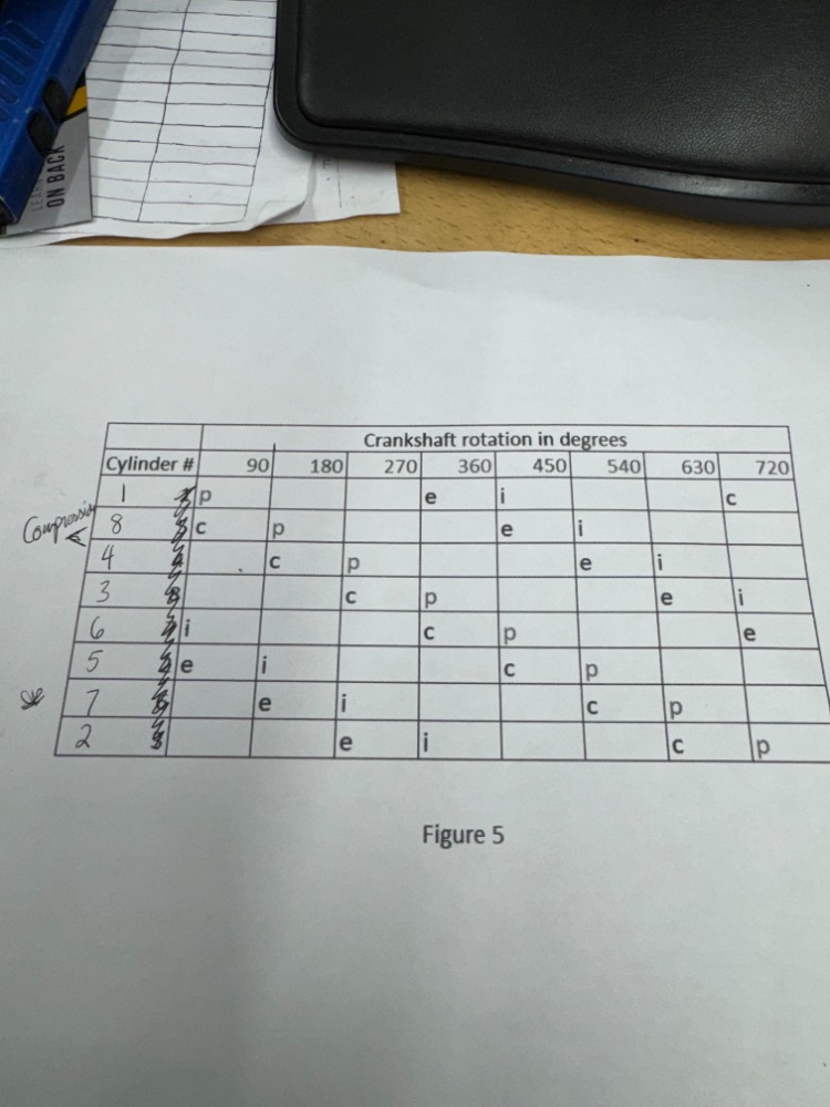
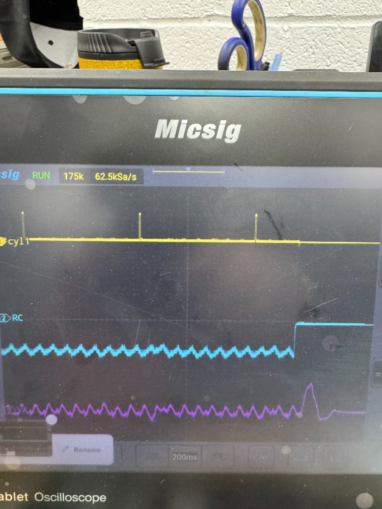
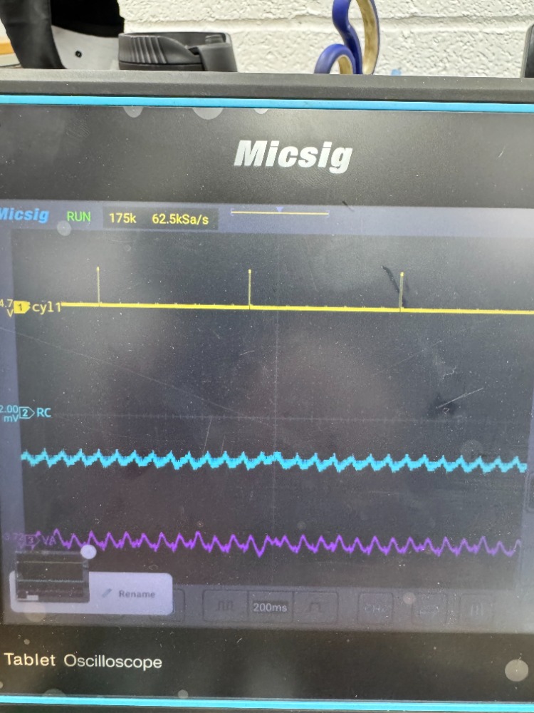
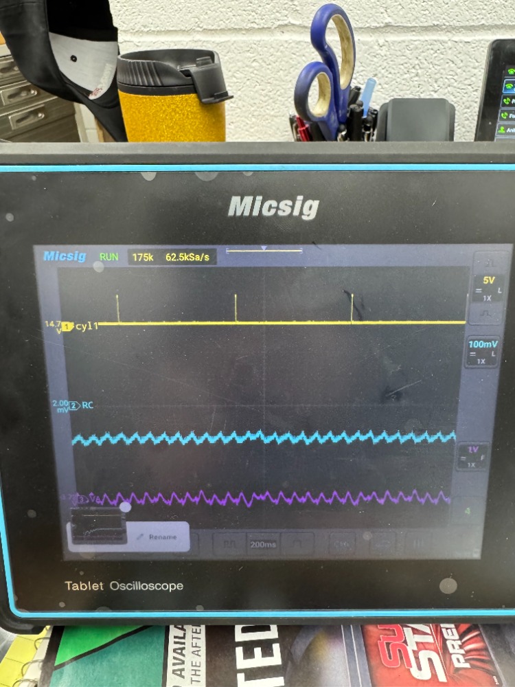
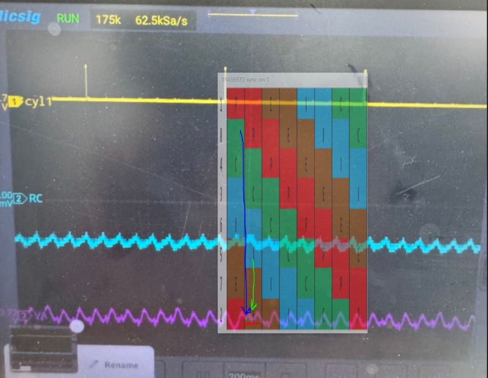
Forcing myself to learn the O scope. We have a misfire on cylinder 8 that is intermittent. We are feeling mechanical in nature so we went to this testing that we learned from Eric Ziegler. WE have coil one for reference, RC and VA sensor attached. I have also attached a piston location chart for reference. My gut is telling me I have valve train issues or a wiped cam. I need help identifying which cylinder is causing the deviation in the vacuum signal, as it isnt lining up with the piston location chart for cylinder 8. Also, the RC deviation is the opposite of low compression.
Please Log in or Create an account to join the conversation.
- Chad
-

- Offline
- Moderator
-

- I am not a parts changer.
Less
More
- Posts: 2173
- Thank you received: 727
1 year 3 months ago - 1 year 3 months ago #73813
by Chad
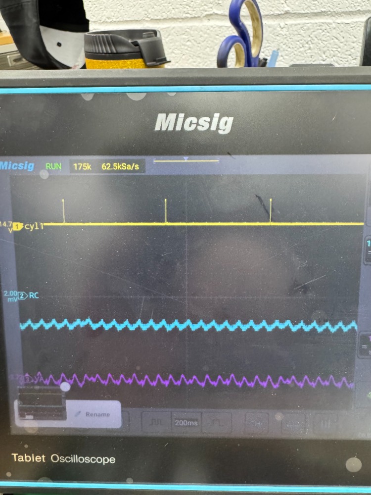
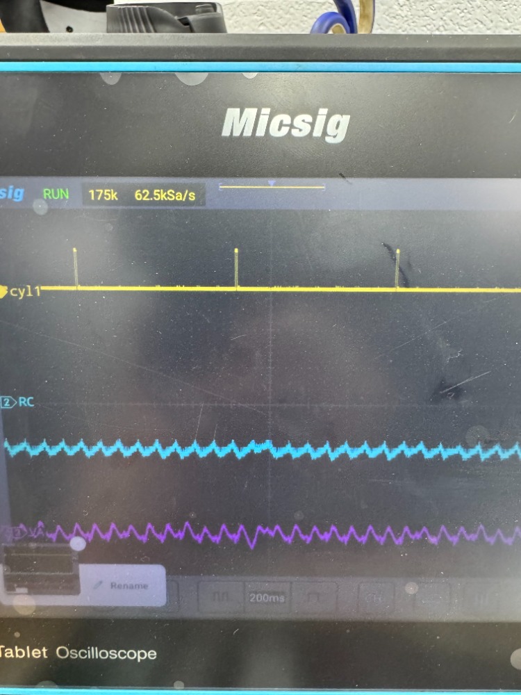
If the RC is a voltage waveform take from the positive battery post, the waveform will be upside-down, compared to an Amperage waveform. An invert function will flip the waveform over.
Here, I have inverted your RC waveform.
As for your intake vacuum pulse waveform, verify that the polarity of the sensor is so that a vacuum makes the trace go down, and pressure makes the trace go up. Also, I'd like to see a longer capture to try and see some more repetition.
If you lower the voltage scale on the scope, it will make your waveforms taller on the screen, magnifying and making it easier to see subtle differences in the individual vacuum pulls.
"Knowledge is a weapon. Arm yourself, well, before going to do battle."
"Understanding a question is half an answer."
I have learned more by being wrong, than I have by being right.")
Replied by Chad on topic Please help me interpret these waveforms for a misfire.
It looks like your RC waveform is inverted/upside-down. If you are using and amp clamp, make sure that the arrow is pointing in the direction of conventional theory current flow. ( If you are on the positive battery cable, the arrow should point AWAY from the battery. If you are on the negative battery cable, the arrow should point TOWARD the battery.the RC deviation is the opposite of low compression
If the RC is a voltage waveform take from the positive battery post, the waveform will be upside-down, compared to an Amperage waveform. An invert function will flip the waveform over.
Here, I have inverted your RC waveform.
As for your intake vacuum pulse waveform, verify that the polarity of the sensor is so that a vacuum makes the trace go down, and pressure makes the trace go up. Also, I'd like to see a longer capture to try and see some more repetition.
If you lower the voltage scale on the scope, it will make your waveforms taller on the screen, magnifying and making it easier to see subtle differences in the individual vacuum pulls.
"Knowledge is a weapon. Arm yourself, well, before going to do battle."
"Understanding a question is half an answer."
I have learned more by being wrong, than I have by being right.
Last edit: 1 year 3 months ago by Chad.
The following user(s) said Thank You: juergen.scholl
Please Log in or Create an account to join the conversation.
- All Okay Auto
-
Topic Author
- Offline
- New Member
-
Less
More
- Posts: 12
- Thank you received: 0
1 year 3 months ago #73817
by All Okay Auto
Replied by All Okay Auto on topic Please help me interpret these waveforms for a misfire.
The inversion makes sense. I cant believe I made that mistake.
Please Log in or Create an account to join the conversation.
- All Okay Auto
-
Topic Author
- Offline
- New Member
-
Less
More
- Posts: 12
- Thank you received: 0
1 year 3 months ago #73818
by All Okay Auto
Replied by All Okay Auto on topic Please help me interpret these waveforms for a misfire.
So my question to you is with the VA sensor deviation How can I tell what cylinder is causing it? Using the piston chart, it isn't making sense to me. Thanks for the inversion.
Please Log in or Create an account to join the conversation.
- Chad
-
- Offline
- Moderator
-
- I am not a parts changer.
Less
More
- Posts: 2173
- Thank you received: 727
1 year 3 months ago #73819
by Chad
"Knowledge is a weapon. Arm yourself, well, before going to do battle."
"Understanding a question is half an answer."
I have learned more by being wrong, than I have by being right.
Replied by Chad on topic Please help me interpret these waveforms for a misfire.
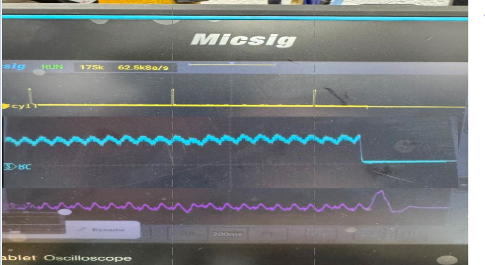
Generally speaking, the low cylinder in your RC waveform is the problem cylinder. In this case, it looks like cylinder #8.
When there is compression loss, the compression has to go into one of four possible locations:
1. Past the intake valve, into Intake manifold
2. Past the exhaust valve, Exhaust manifold
3. Through the head gasket, or less likely, the cylinder wall, into cooling system
4. Or, past the rings, into Crank Case.
I like to put a pulse sensor on each of these locations and compare them all while doing a Relative Compression test.
When you see a low contributing cylinder in the RC, look for a corresponding pressure spike in one of the 4 locations.
What I notice about your RC is that the low cylinder, #8, is not consistently low. It seems to come and go. This may suggest a valve that seals well, sometimes. And, not so well, at other times.
I may, or may not, be right (more testing would need to be done to confirm, or disprove my suspicions) but, what I am seeing is that when #8 comes up on TDC of compression, the loss of compression may be going into the intake, adding volume to the intake manifold as cylinder #5 begins its intake stroke. With #8 adding volume, the intake pull of #5 does not pull as deep of a vacuum.
To prove this, you can roll cylinder #8 up on TDC compression, remove the spark plug, use a rubber tipped air gun to blast air into the cylinder. Can you see the blasts in the intake manifold with the pulse sensor? If not, move the pulse sensor to the tail pipe and blast the cylinder, again. If you can see the blast in the tail pipe, the exhaust valve has leakage. This is my pulse sensor version of a leak-down test.
An in-cylinder cranking compression test with a pressure transducer ( NOT a pulse sensor ) may show the inconsistent high-low compression of cylinder #8.
You could, also, use an ignition waveform to look for hash in the burn line that would indicate valve leakage.
When there is compression loss, the compression has to go into one of four possible locations:
1. Past the intake valve, into Intake manifold
2. Past the exhaust valve, Exhaust manifold
3. Through the head gasket, or less likely, the cylinder wall, into cooling system
4. Or, past the rings, into Crank Case.
I like to put a pulse sensor on each of these locations and compare them all while doing a Relative Compression test.
When you see a low contributing cylinder in the RC, look for a corresponding pressure spike in one of the 4 locations.
What I notice about your RC is that the low cylinder, #8, is not consistently low. It seems to come and go. This may suggest a valve that seals well, sometimes. And, not so well, at other times.
Using the piston chart, it isn't making sense to me.
I may, or may not, be right (more testing would need to be done to confirm, or disprove my suspicions) but, what I am seeing is that when #8 comes up on TDC of compression, the loss of compression may be going into the intake, adding volume to the intake manifold as cylinder #5 begins its intake stroke. With #8 adding volume, the intake pull of #5 does not pull as deep of a vacuum.
To prove this, you can roll cylinder #8 up on TDC compression, remove the spark plug, use a rubber tipped air gun to blast air into the cylinder. Can you see the blasts in the intake manifold with the pulse sensor? If not, move the pulse sensor to the tail pipe and blast the cylinder, again. If you can see the blast in the tail pipe, the exhaust valve has leakage. This is my pulse sensor version of a leak-down test.
An in-cylinder cranking compression test with a pressure transducer ( NOT a pulse sensor ) may show the inconsistent high-low compression of cylinder #8.
You could, also, use an ignition waveform to look for hash in the burn line that would indicate valve leakage.
"Knowledge is a weapon. Arm yourself, well, before going to do battle."
"Understanding a question is half an answer."
I have learned more by being wrong, than I have by being right.
The following user(s) said Thank You: Noah, juergen.scholl, Tutti57
Please Log in or Create an account to join the conversation.
- All Okay Auto
-
Topic Author
- Offline
- New Member
-
Less
More
- Posts: 12
- Thank you received: 0
1 year 3 months ago #73901
by All Okay Auto
Replied by All Okay Auto on topic Please help me interpret these waveforms for a misfire.
I had this come to me this morning and went to add it to the thread, and you and I are in agreement. You beat me to it. WE did an incyl cranking and running. We had one difference in compression cranking, and captured about 24 with nothing noticeable on the peak. The waveform looked really good, but I'll post what I got.
Please Log in or Create an account to join the conversation.
Time to create page: 0.268 seconds