99 ford contour 2.5 no start
- Dave101
-
 Topic Author
- Offline
- Premium Member
-

- Show me what it's not!!
- Posts: 110
- Thank you received: 7
Please Log in or Create an account to join the conversation.
- Chad
-

- Offline
- Moderator
-

- I am not a parts changer.
- Posts: 2181
- Thank you received: 732
"Knowledge is a weapon. Arm yourself, well, before going to do battle."
"Understanding a question is half an answer."
I have learned more by being wrong, than I have by being right.
")

Please Log in or Create an account to join the conversation.
- Chad
-
- Offline
- Moderator
-
- I am not a parts changer.
- Posts: 2181
- Thank you received: 732
"Knowledge is a weapon. Arm yourself, well, before going to do battle."
"Understanding a question is half an answer."
I have learned more by being wrong, than I have by being right.
Please Log in or Create an account to join the conversation.
- Dave101
-
Topic Author
- Offline
- Premium Member
-
- Show me what it's not!!
- Posts: 110
- Thank you received: 7
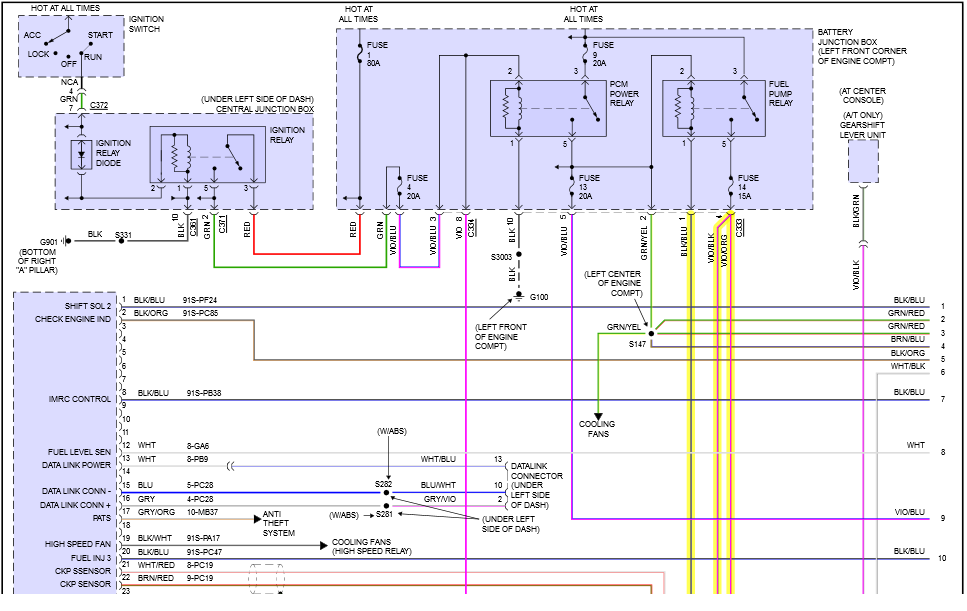
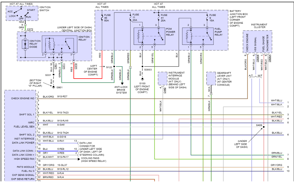
I've got it now. The first thing I did was go to the relay. Relay has a constant + going to it. I figured The PMC was controlling the relay with a negative. This diagram confirms that. I am a little concerned that I activated the relay manually with no activity from the fuel pump. I used a UACTIVATE from aeswave.com and also hooked a low amp probe at the relay with no results. I think I am looking at multiple problems here. Thanks again for the diagram.
Please Log in or Create an account to join the conversation.
- Chad
-
- Offline
- Moderator
-
- I am not a parts changer.
- Posts: 2181
- Thank you received: 732
"Knowledge is a weapon. Arm yourself, well, before going to do battle."
"Understanding a question is half an answer."
I have learned more by being wrong, than I have by being right.
Please Log in or Create an account to join the conversation.
- Dave101
-
Topic Author
- Offline
- Premium Member
-
- Show me what it's not!!
- Posts: 110
- Thank you received: 7
I did check fuse 14 and it was good. Inertia switch was where I was going next. The only problem that I have at this point is I don't have the violet/orange wire on the fuel pump as described in the wiring diagram. Any ideas?pole71 wrote: Check fuse 14. When you activate the relay, does fuse 14 have battery voltage on BOTH test contacts? If it does, check/reset the inertia switch. Finally, check the Fuel pump ground.
Please Log in or Create an account to join the conversation.
- Chad
-
- Offline
- Moderator
-
- I am not a parts changer.
- Posts: 2181
- Thank you received: 732
"Knowledge is a weapon. Arm yourself, well, before going to do battle."
"Understanding a question is half an answer."
I have learned more by being wrong, than I have by being right.
Please Log in or Create an account to join the conversation.
- Dave101
-
Topic Author
- Offline
- Premium Member
-
- Show me what it's not!!
- Posts: 110
- Thank you received: 7
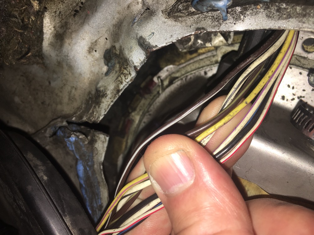
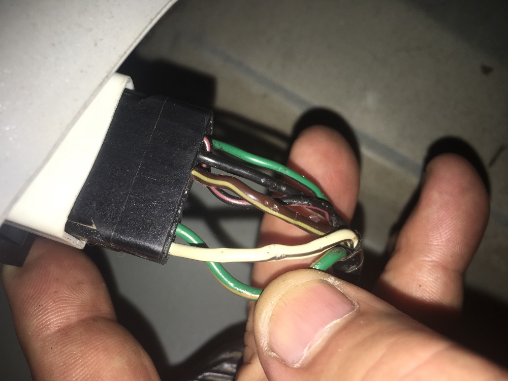
Not in the shop now so bear with me. I know the one's I were assuming were the power and ground to the pump was a brown/green wire and a white and blue. There is also what looks like a fuel pump module in the trunk. I haven't checked for the inertia switch yet. That will be first thing in the morning.pole71 wrote: What colors DO you have at the Fuel pump? What colors at the inertia switch?
Please Log in or Create an account to join the conversation.
- Dave101
-
Topic Author
- Offline
- Premium Member
-
- Show me what it's not!!
- Posts: 110
- Thank you received: 7
Please Log in or Create an account to join the conversation.
- Dave101
-
Topic Author
- Offline
- Premium Member
-
- Show me what it's not!!
- Posts: 110
- Thank you received: 7
Please Log in or Create an account to join the conversation.
- Chad
-
- Offline
- Moderator
-
- I am not a parts changer.
- Posts: 2181
- Thank you received: 732

"Knowledge is a weapon. Arm yourself, well, before going to do battle."
"Understanding a question is half an answer."
I have learned more by being wrong, than I have by being right.
Please Log in or Create an account to join the conversation.
- Chad
-
- Offline
- Moderator
-
- I am not a parts changer.
- Posts: 2181
- Thank you received: 732
"Knowledge is a weapon. Arm yourself, well, before going to do battle."
"Understanding a question is half an answer."
I have learned more by being wrong, than I have by being right.
Please Log in or Create an account to join the conversation.
- Tyler
-

- Offline
- Moderator
-
- Full time HACK since 2012
- Posts: 6124
- Thank you received: 1541

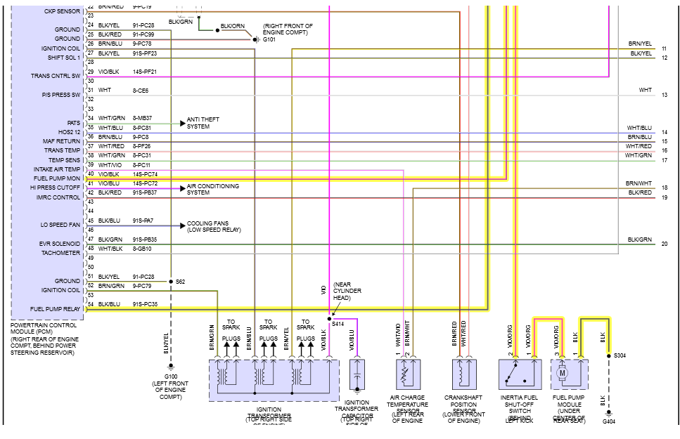
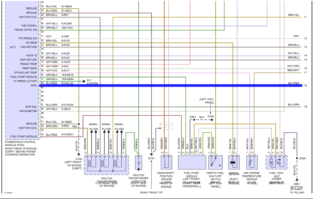
Dave101, I'd suggest checking voltage at the white/black and brown/yellow wires at the module during cranking. These are the pump power and ground provided by the module. OR, you can check the green/orange and black wires for voltage during cranking. These are the module power and ground.
Either check will help point you in the right direction.
Please Log in or Create an account to join the conversation.
- Dave101
-
Topic Author
- Offline
- Premium Member
-
- Show me what it's not!!
- Posts: 110
- Thank you received: 7
Tyler wrote: Thanks, pole71! I was trying to dig up that same diagram, too. BBB Industries doesn't seem to have it.
Dave101, I'd suggest checking voltage at the white/black and brown/yellow wires at the module during cranking. These are the pump power and ground provided by the module. OR, you can check the green/orange and black wires for voltage during cranking. These are the module power and ground.
Either check will help point you in the right direction.
Thank You both for the information. It would have taken a lot longer to figure out what was wrong with this without your help. Just for my knowledge, what was the difference in the two diagrams?
Please Log in or Create an account to join the conversation.
- Tyler
-
- Offline
- Moderator
-
- Full time HACK since 2012
- Posts: 6124
- Thank you received: 1541
Please Log in or Create an account to join the conversation.
- Chad
-
- Offline
- Moderator
-
- I am not a parts changer.
- Posts: 2181
- Thank you received: 732
Dave101 wrote: Just for my knowledge, what was the difference in the two diagrams?
Early or Late production. The First diagram was Early production. You, apparently, have Late production. Sometime in the production of '99 Contour, they added the module.
"Knowledge is a weapon. Arm yourself, well, before going to do battle."
"Understanding a question is half an answer."
I have learned more by being wrong, than I have by being right.
Please Log in or Create an account to join the conversation.
- Dave101
-
Topic Author
- Offline
- Premium Member
-
- Show me what it's not!!
- Posts: 110
- Thank you received: 7
Please Log in or Create an account to join the conversation.
- Tyler
-
- Offline
- Moderator
-
- Full time HACK since 2012
- Posts: 6124
- Thank you received: 1541
") Glad to hear it's fixed!
Glad to hear it's fixed! Please Log in or Create an account to join the conversation.