[FIXED] 2001 Ram won't start unless you give it a drink
- trat50
-
 Topic Author
- Offline
- Junior Member
-

- Posts: 20
- Thank you received: 12
Here is a weird one. 2001 Ram 1500 5.9 4x4 auto. Cranks - no start. Has spark & fuel pump. Poured fuel in throttle body and it started & kept running normally. Shut it off & again it would not start.. again primed throttle body. Started & ran normal. 1 code - P8138, no voltage from ASD relay to PCM. Replaced ASD relay - no change.
ScannerDanner
Get it to not start again and check power at the injectors while cranking. Give me a voltage number
trat50
Battery voltage @ 12.15 volts. Ground = negative battery terminal in all cases.
Cranking/no start - power at Injectors:
Green/orange stripe = 10.26 volts (10.31 to 10.22)
Yellow/white stripe = 0 volts (momentary surge to .02)
ScannerDanner
To be clear. One injector wire is reading battery voltage and the other is 0 all the time? And is that just one injector you tested?
It should be 12 and 12 not 12 and 0
trat50
Yes, that's correct - one injector wire reads 10.26 volts when cranking & the other injector wire reads 0 volts when cranking. Yes, I only tested the injector wires on cylinder # 1. No, I did not get 12v and 12v, I got 10.26v and 0v.
ScannerDanner
The ASD circuit code has me concerned. It is what is supplying voltage to the injectors and other components. With just the key on on your system the two injector wires should read 0 and 0 (ASD is not energized until there is an RPM signal). Initial key on it will turn on for 1-2 seconds then turn back off until there is RPM.
Anyway, once you start cranking, your injectors will start pulsing and it is too fast for a digital voltmeter to see it, so one wire will show battery voltage (from ASD circuit) and the other will be pulsing to ground but will also show battery voltage (a few hundred millivolts less due to the quick pulses to ground by the PCM).
So basically you should be reading 12 and 12 cranking.
For you to have 12 and 0 on the injector you tested means either the injector winding is open (bad injector) or the wiring is shorted to ground in which case the injector is on all the time and will flood the cylinder with fuel.
The fact that it is a multi-port system and it is a no start, says to me it is NOT an open injector, they would all have to be open for it to not start and that you did not mention a flooded engine or cylinder full of gas plus again, it would have to be all of the cylinders for it to be a no start. All of this tells me you didn't do the injector voltage measurements correctly. The test should be done with the injector plugged in and backprobing the connector.
trat50
OK, I understand. Yes, I did the test incorrectly. (I unplugged the injector wires from injector and tested that way.) I just watched 3 more of your videos - I'll go get a "T-pin" and do the test correctly. Sorry.
ScannerDanner Premium
No problem man. Use this test, it will be better. Disconnect the injector and put an incandescent type test light between the two terminals of the injector. You'll need to be creative with a pin on the alligator clip for one side. Just DO NOT let them touch (the test light pointed end and the pin). Crank the engine over, the light should pulse on and off.
trat50
OK, went shopping, bought T-pins & incandescent test light.
All of the following tests were done while CRANKING:
Test light on 2 terminals of disconnected injector lead = NO flash.
Voltage of 2 wires to ground of connected injector: 10.3 & 10.2.
..and this is the kicker: Voltage across battery terminals:
At rest = 12.38 volts. CRANKING = 10.5 volts. ..bad battery?
(I disconnected battery and am charging it right now).
ScannerDanner
The voltage of 10.3 & 10.2 was cranking right?
If so your battery is fine, you have no injector pulse. The "no voltage from the ASD relay" code is the path we need to walk now.
Post this to my forum so we can look at diagrams and stuff okay?
www.scannerdanner.com
trat50
Yes, that was cranking. I will post that to the forum now.
I charged up the battery. Reading 13.5v fresh off the charger and not cranking. Tried again - no start.
Please Log in or Create an account to join the conversation.
- Tyler
-

- Offline
- Moderator
-

- Full time HACK since 2012
- Posts: 6124
- Thank you received: 1541
So the ASD relay appears to be working, despite the code. No insult meant here, but are you sure you got that trouble code right? P8138 doesn't exist, as far as I can tell. I would have expected something like P0688 ASD Relay Circuit Malfunction.
Anyway, if your code description is correct, then it sounds like the PCM isn't seeing voltage on it's ASD relay output state monitor. Simply, the PCM has a dedicated circuit to check that the ASD relay is working or not. I grabbed the diagram for reference:
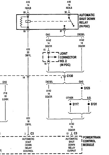
It's tough to get the whole diagram in one shot, so just know that the top two wires come from fuse #6 in the Power Distribution Center. The output state monitor would be at the dark green/orange wire, pin 12 connector 3 of the PCM. This wire should be in between a orange/white wire and a yellow/red wire in the PCM connector. You'll want to backprobe that dark green/orange wire (carefully) and use your voltmeter to get a reading during cranking. You can also connect your test light to B-, hook it to the back probe, and do the same thing. The light should illuminate brightly.
Let us know how that test goes, and if that code is correct, and we can help you further!
Please Log in or Create an account to join the conversation.
- trat50
-
Topic Author
- Offline
- Junior Member
-
- Posts: 20
- Thank you received: 12
1.) Back probe pin #12 on PCM connector #3 and check voltage while cranking.
2.) On same back probed pin (pin #12) I will next test using my test light to the same back probe (T-pin), again while cranking.
Please Log in or Create an account to join the conversation.
- Tyler
-
- Offline
- Moderator
-
- Full time HACK since 2012
- Posts: 6124
- Thank you received: 1541
Please Log in or Create an account to join the conversation.
- trat50
-
Topic Author
- Offline
- Junior Member
-
- Posts: 20
- Thank you received: 12
Just got back from testing. Here are the results:
Redid code check: It is still giving just 1 code. I am reading the codes with my Autel MaxiScan MS310.
It says it is a Manufacturer specific code. I choose Chrysler for manufacturer, (Dodge is not listed).
It gives me code P1389 #D1 Chrysler "No ASD Relay Output Voltage at PCM".
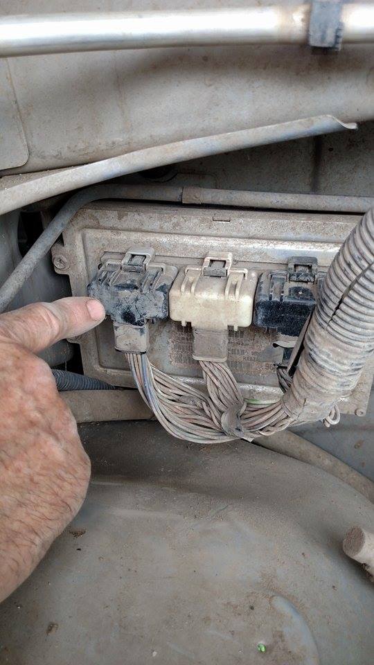
I found connector #3 on PCM. (See Photo) ..and pulled connector just to find Dark green/orange wire on Pin 12.
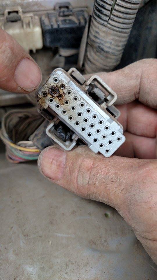
Here is what I found on the inside of the connector (See Photo):
Looks like pin #12 has been getting hot! :ohmy:
I went ahead and did the tests with a T-pin, backprobing the Dark Green/orange wire. Results:
Voltage (cranking) = 10.83 volts
Test light = lights up when cranking
(also lights up with ignition just turned to "on" position).
Thanks Tyler,
Tom
Please Log in or Create an account to join the conversation.
- Inge Jeppesen
-

- Offline
- Junior Member
-
- Ford master tech.
- Posts: 38
- Thank you received: 3
Please Log in or Create an account to join the conversation.
- Tyler
-
- Offline
- Moderator
-
- Full time HACK since 2012
- Posts: 6124
- Thank you received: 1541
I think I know what's going on here, but let me get on my laptop and check the wiring diagram. Unfortunately, this may end with PCM replacement and repairing that connector

Please Log in or Create an account to join the conversation.
- Tyler
-
- Offline
- Moderator
-
- Full time HACK since 2012
- Posts: 6124
- Thank you received: 1541
Thanks for rechecking that code, 'cause that came in very handy! I ran the new code through iATN, just trying to see what info I could find. I took a screen shot of a reply to a TechHelp post about our exact situation on another '01 Ram:

Now isn't that interesting? I knew the PCM controlled alternator field strength directly, but I did NOT know that pin 12 was the source. For reference, this is the alternator diagram:
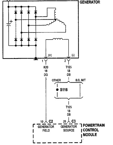
Sure enough, power comes out of the PCM to the alternator (generator source) on another pin of the same connector. The PCM then grounds the generator field pin to control alternator output. I'm going over all this because I'm worried about your replacement PCM getting damaged by a fault in the alternator field circuit. I think we've found the cause of the no start, but I'm not sure we've found the cause of the PCM failure.
I'm going to look up the resistance specification for the alternator tomorrow. If you have the opportunity, I'd like you to check resistance between pin 12 and 25 of C3, key off and PCM disconnected. Also check resistance between pin 12 and ground, PCM disconnected. Note the readings and let me know what you find!
Please Log in or Create an account to join the conversation.
- trat50
-
Topic Author
- Offline
- Junior Member
-
- Posts: 20
- Thank you received: 12
Please Log in or Create an account to join the conversation.
- Tyler
-
- Offline
- Moderator
-
- Full time HACK since 2012
- Posts: 6124
- Thank you received: 1541

We'll use that as a guideline, but not absolute truth.
Please Log in or Create an account to join the conversation.
- trat50
-
Topic Author
- Offline
- Junior Member
-
- Posts: 20
- Thank you received: 12
Check resistance between pin 12 & pin 25 of connector #3
With key off & PCM disconnected <~~(I disconnected ALL 3 PCM connectors).
RESULTS: Open Circuit - no connection at all.
Check resistance between pin 12 of connector 3 and ground
With key off & PCM disconnected <~~(I disconnected ALL 3 PCM connectors).
RESULTS: 3.4 ohms.
Please Log in or Create an account to join the conversation.
- Tyler
-
- Offline
- Moderator
-
- Full time HACK since 2012
- Posts: 6124
- Thank you received: 1541
trat50 wrote: OK Tyler, I just did those 2 tests.
Check resistance between pin 12 & pin 25 of connector #3
With key off & PCM disconnected <~~(I disconnected ALL 3 PCM connectors).
RESULTS: Open Circuit - no connection at all.
Check resistance between pin 12 of connector 3 and ground
With key off & PCM disconnected <~~(I disconnected ALL 3 PCM connectors).
RESULTS: 3.4 ohms.
Oh wow, I'm such an idiot...

I'm really sorry man, I told you the completely wrong wires to check. Completely my fault, got my pins mixed around, not paying enough attention. Now that I realize how I messed up, your measurements make perfect sense! Wonder if anyone else caught my mistake, lol.
Can I get you to do some new measurements? What we actually want to do is measure resistance between pin 25 of C3 and pin 10 of C2. Check the alternator diagram for reference. PCM unplugged, as always. Also check resistance to ground at pin 25. Thiso will tell us if the alternator is shorted, or if there's a short to ground on the power feed to the alternator.
Again, my sincere apologies. I'll keep my head in the game next time.
Please Log in or Create an account to join the conversation.
- trat50
-
Topic Author
- Offline
- Junior Member
-
- Posts: 20
- Thank you received: 12
")
I will have to do those tests tomorrow morning.
Thank you, Tom
Please Log in or Create an account to join the conversation.
- trat50
-
Topic Author
- Offline
- Junior Member
-
- Posts: 20
- Thank you received: 12
(These measurements were all done with all 3 connectors disconnected from PCM and Key Off.)
Resistance from pin 25 of C3 to pin 10 of C2:
RESULTS: 6.4 ohms
Resistance from pin 25 of C3 to ground:
RESULTS: Open circuit, no connection.
Please Log in or Create an account to join the conversation.
- Tyler
-
- Offline
- Moderator
-
- Full time HACK since 2012
- Posts: 6124
- Thank you received: 1541
trat50 wrote: Hi Tyler, Here are the results -
(These measurements were all done with all 3 connectors disconnected from PCM and Key Off.)
Resistance from pin 25 of C3 to pin 10 of C2:
RESULTS: 6.4 ohms
Resistance from pin 25 of C3 to ground:
RESULTS: Open circuit, no connection.
Nice, thanks sir! Those are pretty much the results I was hoping for. We now know that the power feed to the alternator isn't grounded, and that the alternator field winding isn'the shorted (for now).
Unless anyone else can find a reason not to, I think you're good to go on PCM replacement and connector repair. My biggest concern is that the alternator field winding is intermittently shorting (when hot, possibly), and could cause another failure. For that reason, I'd suggest doing an alternator at the same time.
There ARE other ways we could verify the alternator field circuit. Ohms Law says that circuit should draw around two amps when full fielded. But, to measure that, you'd either have to rig an ammeter in series, or get an inductive amp probe. This also won't rule out an intermittent problem.
Not a cheap repair, I'm sorry sir
Plus, the replacement PCM will likely require VIN programming. Please Log in or Create an account to join the conversation.
- ws2664
-
- Offline
- New Member
-

- Posts: 4
- Thank you received: 2
Please Log in or Create an account to join the conversation.
- trat50
-
Topic Author
- Offline
- Junior Member
-
- Posts: 20
- Thank you received: 12
The connector should not be a problem. I have tomorrow off and my favorite junkyard is open all day.
I am 99% sure the other 2 connectors are OK, but I'll check. Soldering Iron and heat shrink tubing are my friends.
We will replace both the alternator and computer. This is my daughters truck. She took the pictures for me.
Thanks ws2664 for the heads up. I am interested in how your Ram turns out on this deal.
Please Log in or Create an account to join the conversation.
- Tyler
-
- Offline
- Moderator
-
- Full time HACK since 2012
- Posts: 6124
- Thank you received: 1541
trat50, sounds like you've got a plan
") Maybe take your multimeter to the junkyard? Just to check the replacement alternator for a short before leaving. Can't wait to hear how everything turns out!
Maybe take your multimeter to the junkyard? Just to check the replacement alternator for a short before leaving. Can't wait to hear how everything turns out! Please Log in or Create an account to join the conversation.
- ScannerDanner
-

- Offline
- Administrator
-

- Religion says do, Jesus says done!
- Posts: 975
- Thank you received: 500
Thanks so much trat50 for posting this here. It really helps me out a lot! And now you see why. These guys are awesome here aren't they?
Don't be a parts changer!
Please Log in or Create an account to join the conversation.
- trat50
-
Topic Author
- Offline
- Junior Member
-
- Posts: 20
- Thank you received: 12

Please Log in or Create an account to join the conversation.