2008 Jetta 2.5, voltage at CKP signal wire with sensor unplugged
- lmg866
-
 Topic Author
- Offline
- Senior Member
-

- Posts: 56
- Thank you received: 2
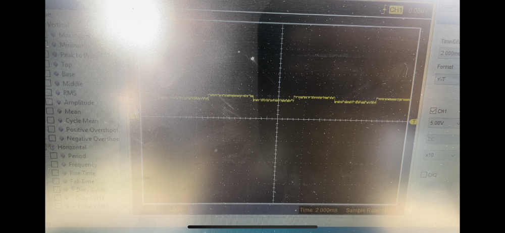
Scoping the signal wire while cranking, I see the 5v signal get pulled down to about 4v in a square wave pattern, where I think it should get pulled down to zero (scope pic attached). I am guessing this means the sensor is functioning properly, but it is not able to give enough wave form amplitude to the ECM to provide a crank signal because of the 5v supplied to the signal wire.
Any thoughts on how to proceed?
Please Log in or Create an account to join the conversation.
- Tutti57
-

- Offline
- Platinum Member
-

- Posts: 1098
- Thank you received: 253
I'd be good to get a known good wave form to compare, but it's unlikely that the 1v change you're seeing is normal, so I think you're on to something here. I'm thinking either the sensor is bad or maybe the airgap is not correct, and isn't able to be pulled down all the way.
Please Log in or Create an account to join the conversation.
- lmg866
-
Topic Author
- Offline
- Senior Member
-
- Posts: 56
- Thank you received: 2
Please Log in or Create an account to join the conversation.
- Tutti57
-
- Offline
- Platinum Member
-
- Posts: 1098
- Thank you received: 253
Please Log in or Create an account to join the conversation.
- lmg866
-
Topic Author
- Offline
- Senior Member
-
- Posts: 56
- Thank you received: 2
Please Log in or Create an account to join the conversation.
- Chad
-

- Offline
- Moderator
-

- I am not a parts changer.
- Posts: 2174
- Thank you received: 727
How are you testing the ground? I would connect a second scope channel to see a waveform of the sensor ground, along with the sensor signal.With key on I have 5v at pin 1 and 5v at pin 2 and good ground with the connector back probed and the sensor connected.
This suggests a pull-down design.Scoping the signal wire while cranking, I see the 5v signal get pulled down to about 4v in a square wave pattern
can you pull the 5 volts that is on the signal wire to ground with an incandescent test light connected to battery negative? Or, does the test light, dimmly, glow?I suppose the wire could be shorted to a different 5v wire.
"Knowledge is a weapon. Arm yourself, well, before going to do battle."
"Understanding a question is half an answer."
I have learned more by being wrong, than I have by being right.
")
Please Log in or Create an account to join the conversation.
- lmg866
-
Topic Author
- Offline
- Senior Member
-
- Posts: 56
- Thank you received: 2
I simply verified continuity with a multimeter. I will try a separate channel on the ground wire while cranking. What should I be looking for?
In the incandescent test light example, it seems like I am trying to load the circuit some. What would a bright or dim result suggest?
Please Log in or Create an account to join the conversation.
- Chad
-
- Offline
- Moderator
-
- I am not a parts changer.
- Posts: 2174
- Thank you received: 727
You want to see the voltage on the ground wire remain less than 100 mV (0.1 volt). If you see a square wave with an amplitude of more than 100 mV, you have a bad ground.I will try a separate channel on the ground wire while cranking. What should I be looking for?
In the incandescent test light example, it seems like I am trying to load the circuit some. What would a bright or dim result suggest?
If the 5v on the signal wire is a bias voltage, and can be pulled down to ground, this would suggest that:
1) This IS a pull-down circuit design
2) The senor is bad, and cannot pull the signal down. Or,
3) You have a bad sensor ground.
If the test light glows, you have a short to power.
"Knowledge is a weapon. Arm yourself, well, before going to do battle."
"Understanding a question is half an answer."
I have learned more by being wrong, than I have by being right.
Please Log in or Create an account to join the conversation.
- lmg866
-
Topic Author
- Offline
- Senior Member
-
- Posts: 56
- Thank you received: 2
Before I saw your reply, I ended up buying a new sensor. This solved the issue. Next time I’ll know more about what to do with the test results I saw. Thanks again!
Please Log in or Create an account to join the conversation.