2011 Subaru Forester xt CMP waveform questions
- Jostr
-
 Topic Author
- Offline
- New Member
-

- Posts: 18
- Thank you received: 1
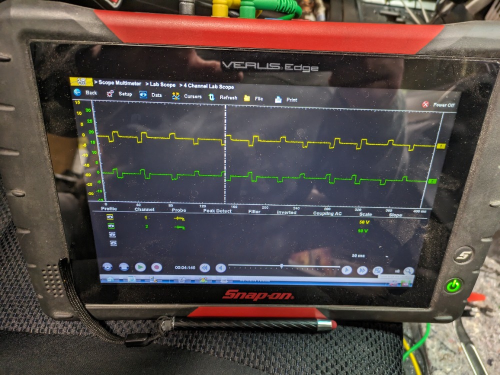
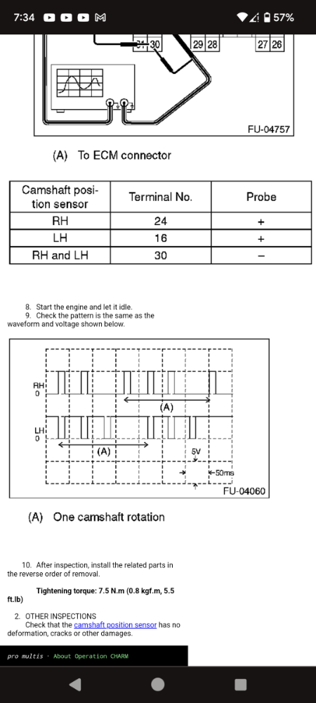
so I have a 2011 Subaru Forester xt in with what a believe is jumped time, but I'm not sure.im still new to scope usage but hoping to get more confident. I've got p0301-p0304 and p0340 CMP sensor code. When I use the scope to get a waveform. It looks off from the service data example I have. Any info/ help would be greatly appreciated.
Please Log in or Create an account to join the conversation.
- Noah
-

- Offline
- Moderator
-

- Give code definitions with numbers!
- Posts: 4959
- Thank you received: 1111
The scope is set to 50v scale, that's too much. I would probably go 10v considering we're expecting a 5v square wave.
Also, exactly what channel is what sensor? Are these intake cams on opposite banks, intake and exhaust on the same bank etc.
"Ground cannot be checked with a 10mm socket"
Please Log in or Create an account to join the conversation.
- Jostr
-
Topic Author
- Offline
- New Member
-
- Posts: 18
- Thank you received: 1
When I set the verus to 5v 50ms per division it shows 50v for some reason. As far as the going below 0v I figure I had a trigger set wrong. Or could a shared scope ground be causing feed back?
Yellow is right hand and green is left hand. So I would think if the timing was correct it should look like the sample from service data.
Please Log in or Create an account to join the conversation.
- Noah
-
- Offline
- Moderator
-
- Give code definitions with numbers!
- Posts: 4959
- Thank you received: 1111
Agreed, however the signal is not being acquired properly.I would think if the timing was correct it should look like the sample from service data.
Misaligned cam timing will result in misaligned waveforms, not completely unexpected voltage levels in the waveforms.
When you have 0v to 5v square wave patterns on the screen, you can compare them to the known good.
Otherwise there is a signal acquisition error using the scope, or something strange happening to cam signal circuits.
"Ground cannot be checked with a 10mm socket"
Please Log in or Create an account to join the conversation.
- Jostr
-
Topic Author
- Offline
- New Member
-
- Posts: 18
- Thank you received: 1
Thank you Noah for your time and experience.
Please Log in or Create an account to join the conversation.
- Chad
-

- Offline
- Moderator
-
- I am not a parts changer.
- Posts: 2129
- Thank you received: 715

could a shared scope ground be causing feed back?
I thought I was getting some kind of back feed because the negative wave matched up perfectly with the other trace positive.
My first thought was a bad scope ground. The two channels look, incredibly, clean to be missing a ground, though...?
When I set the verus to 5v 50ms per division it shows 50v for some reason
Could there be something wrong with your scope? Do you have another hall effect sensor, or different vehicle, available to test?
"Knowledge is a weapon. Arm yourself, well, before going to do battle."
"Understanding a question is half an answer."
I have learned more by being wrong, than I have by being right.
")
Please Log in or Create an account to join the conversation.
- Jostr
-
Topic Author
- Offline
- New Member
-
- Posts: 18
- Thank you received: 1
Please Log in or Create an account to join the conversation.
- Chad
-
- Offline
- Moderator
-
- I am not a parts changer.
- Posts: 2129
- Thank you received: 715
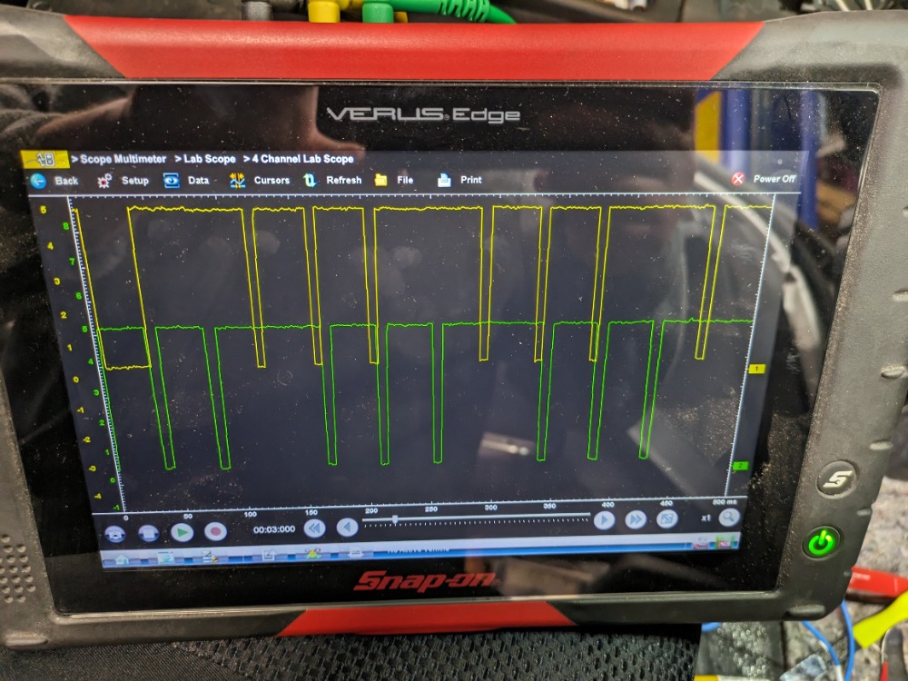
Move this to the negative battery post.ground from yellow lead into pin 30 (ground)
"Knowledge is a weapon. Arm yourself, well, before going to do battle."
"Understanding a question is half an answer."
I have learned more by being wrong, than I have by being right.
Please Log in or Create an account to join the conversation.
- Chad
-
- Offline
- Moderator
-
- I am not a parts changer.
- Posts: 2129
- Thank you received: 715
Looking the waveforms, the wiring diagram, and the way you had your scope referenced to the sensor ground, I suspect you may have an open in the sensor ground circuit, from the computer ---> to the sensors.
To check the sensor grounds, open up another scope channel and connect it to a sensor ground, at the sensor. Voltage on the sensor ground should be less than 100 mV. If you are getting a square wave with an amplitude of more than 100 mV, then you have a bad sensor ground.
"Knowledge is a weapon. Arm yourself, well, before going to do battle."
"Understanding a question is half an answer."
I have learned more by being wrong, than I have by being right.
Please Log in or Create an account to join the conversation.
- Jostr
-
Topic Author
- Offline
- New Member
-
- Posts: 18
- Thank you received: 1
Please Log in or Create an account to join the conversation.
- Jostr
-
Topic Author
- Offline
- New Member
-
- Posts: 18
- Thank you received: 1
Please Log in or Create an account to join the conversation.
- Noah
-
- Offline
- Moderator
-
- Give code definitions with numbers!
- Posts: 4959
- Thank you received: 1111
Certainly looks to be out of time to me when compared to the known good example.
"Ground cannot be checked with a 10mm socket"
Please Log in or Create an account to join the conversation.