2017 Ford F350. P0402 and P0107. Fixed.
- 70monte
-
 Topic Author
- Offline
- Elite Member
-

- Posts: 184
- Thank you received: 26
I scanned it with my scan tool and these two codes came up. P0402 is EGR excessive flow and P0107 is MAP pressure sensor circuit low voltage.
I did some research online and there was information that stated that the EGR valve uses information from the MAP sensor to operate correctly.
The voltage reading with my scanner showed 0 volts for the MAP sensor. I then used my voltmeter and lightly touched the three pins of the connector and read 0.014 volts on pins 1 & 2 and 5.0 volts on pin 3. According to the 2016 F350 wiring diagram I could find, pin 3 goes to the EGR valve and the other two pins go to the ECM. I'm not sure if the 2017 has the same wiring setup.
Does anyone have access to the MAP and EGR wiring for a 2017 F350? Thanks.
Please Log in or Create an account to join the conversation.
- Paul P.
-

- Offline
- Platinum Member
-

- Posts: 455
- Thank you received: 195
- 70monte
-
Topic Author
- Offline
- Elite Member
-
- Posts: 184
- Thank you received: 26
Please Log in or Create an account to join the conversation.
- matrintrash
-
- Offline
- New Member
-

- Posts: 2
- Thank you received: 0
Please Log in or Create an account to join the conversation.
- 70monte
-
Topic Author
- Offline
- Elite Member
-
- Posts: 184
- Thank you received: 26
When I was looking at the MAP voltage on the live data, I also had two different PSI pids pulled up and one was fixed at 50 psi and the other one was fixed low at I think about 5 psi. Neither of them responded if you increased the rpms.
Please Log in or Create an account to join the conversation.
- Tyler
-

- Offline
- Moderator
-

- Full time HACK since 2012
- Posts: 6064
- Thank you received: 1531
Disconnect the MAP and recheck pin #2 for voltage. If it's at 5-ish volts, the MAP sensor has failed. Sensor time!
If still zero, short pin #3 to pin #2 across a 5K ohm resistor and recheck your scan data. Or, clear the fault codes and reread. You should now have a MAP circuit high code.
Please Log in or Create an account to join the conversation.
- 70monte
-
Topic Author
- Offline
- Elite Member
-
- Posts: 184
- Thank you received: 26
Pin 1: 0.016 volts unplugged and plugged at the MAP connector.
Pin 2: 0.016 volts unplugged and plugged.
Pin 3: 5 volts unplugged and plugged.
Tested at the PCM connector:
Same voltages that I saw at the MAP connector except I did see 0.030 volts at Pin 2 with the truck running. I also used a piercing probe on the Pin 2 wiring at the PCM connector just to verify I was getting the same voltage that I did with back probing the connector.
I don't have any resisters so I was not able to jump Pins 3 & 2.
I don't have a wiring diagram to check the power and grounds at the PCM. The truck only has 32,000 miles on it so I would hate to think the PCM has an issue already.
This truck did have some previous rodent damage that the dealer fixed previously but this is the first time this code has ever set and the truck has been parked at a different property since the previous damage occurred.
I'm going to look around to see if I can see any wiring damage. Thanks for the information.
Please Log in or Create an account to join the conversation.
- Tyler
-
- Offline
- Moderator
-
- Full time HACK since 2012
- Posts: 6064
- Thank you received: 1531
Tested at the PCM connector:
Same voltages that I saw at the MAP connector except I did see 0.030 volts at Pin 2 with the truck running. I also used a piercing probe on the Pin 2 wiring at the PCM connector just to verify I was getting the same voltage that I did with back probing the connector.
I don't have any resisters so I was not able to jump Pins 3 & 2.
Gotcha. As an alternative, you can ohm pin #2 (sensor disconnected) to ground. If it's more than 5K ohms, I'd say you're safe to short #2 and #3 together.
Please Log in or Create an account to join the conversation.
- 70monte
-
Topic Author
- Offline
- Elite Member
-
- Posts: 184
- Thank you received: 26
Please Log in or Create an account to join the conversation.
- 70monte
-
Topic Author
- Offline
- Elite Member
-
- Posts: 184
- Thank you received: 26
Please Log in or Create an account to join the conversation.
- Tyler
-
- Offline
- Moderator
-
- Full time HACK since 2012
- Posts: 6064
- Thank you received: 1531
Tyler, I did the test you requested. K ohms were 102.4 I shorted pins 2 & 3 together and did get a high circuit code of P0108 so the PCM is able to recognize the introduced fault. This test was done with the MAP sensor plugged in.
Perfect! I'd say you're done. The MAP sensor has 5V, ground and signal circuit integrity. The PCM is monitoring the MAP signal circuit correctly. Eyeball the MAP sensor connector for any pin fitment issues, then it's time for a new MAP sensor.
Please Log in or Create an account to join the conversation.
- 70monte
-
Topic Author
- Offline
- Elite Member
-
- Posts: 184
- Thank you received: 26
Please Log in or Create an account to join the conversation.
- 70monte
-
Topic Author
- Offline
- Elite Member
-
- Posts: 184
- Thank you received: 26
I have checked Pin #2 unplugged and plugged and have never seen 5 volts at that pin. It's always around 0. Pin #3 is the only pin I have ever seen 5 volts on.
Is pin #2 the ground signal from the PCM since it's getting 5 volts from Pin #3?
Please Log in or Create an account to join the conversation.
- Tyler
-
- Offline
- Moderator
-
- Full time HACK since 2012
- Posts: 6064
- Thank you received: 1531
Tyler, I wanted to clarify something. This is what you said previously in the post. "Disconnect the MAP and recheck pin #2 for voltage. If it's at 5-ish volts, the MAP sensor has failed. Sensor time!"
I have checked Pin #2 unplugged and plugged and have never seen 5 volts at that pin. It's always around 0. Pin #3 is the only pin I have ever seen 5 volts on.
Is pin #2 the ground signal from the PCM since it's getting 5 volts from Pin #3?
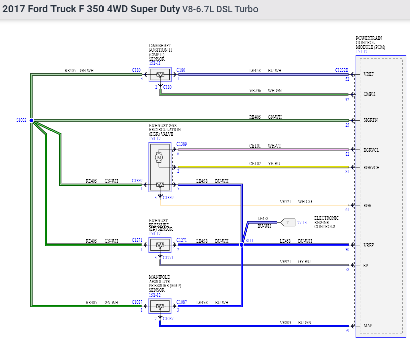
Negative, pin #2 is the signal wire. I grabbed a snip of the OEM diagram for reference:
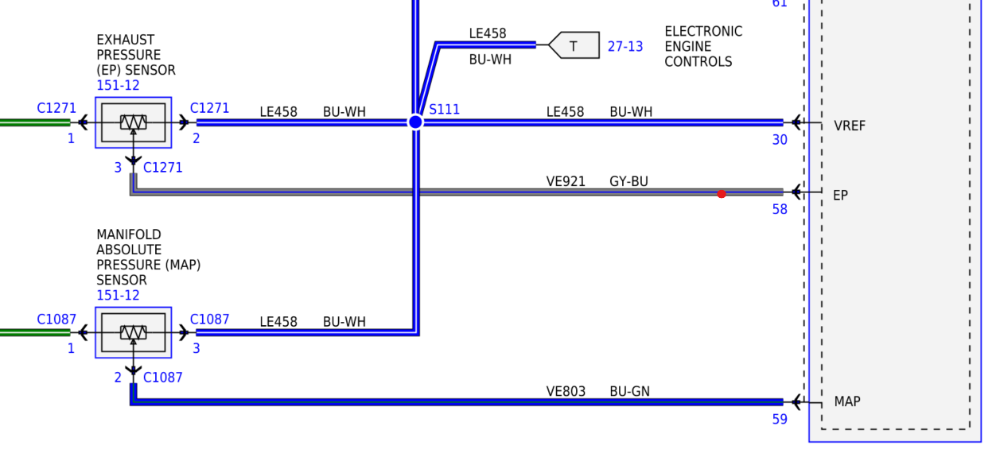
Pin 1 is ground, pin 2 is signal, pin 3 is the 5V reference.
When I suggested that if you found 5V on pin #2, it was with the hope that Ford designed this signal circuit with a 5V bias. Would have made testing a lot easier.

But they didn't, so I suggested shorting between pins to verify signal circuit integrity. You got P0108 with pin 2 and 3 shorted, which means the signal circuit works.
Please Log in or Create an account to join the conversation.
- 70monte
-
Topic Author
- Offline
- Elite Member
-
- Posts: 184
- Thank you received: 26
Please Log in or Create an account to join the conversation.
- 70monte
-
Topic Author
- Offline
- Elite Member
-
- Posts: 184
- Thank you received: 26
I want to thank everyone who commented and especially to Tyler who gave me good direction on where to go.
Please Log in or Create an account to join the conversation.
- Tyler
-
- Offline
- Moderator
-
- Full time HACK since 2012
- Posts: 6064
- Thank you received: 1531
I want to thank everyone who commented and especially to Tyler who gave me good direction on where to go.
Happy to hear it's back to running well.
")
Please Log in or Create an account to join the conversation.