2018 Infiniti Q60 Red Sport 400
- Lvumlow
-
 Topic Author
- Offline
- Junior Member
-

- Posts: 20
- Thank you received: 1
I purchased some troubleshooting equipment and have been trying to get up to speed on some diagnostic strategies. I was hoping someone might be willing to help me with some locations/pin outs and testing strategies to help me find the source of the problem.i am willing to hire someone to work with me remotely or bring the car in if it cannot be resolved on my end. I am a 25 yr veteran PC technician so i feel comfortable with tackling this: just need guidance. I installed all the mods below myself and feel like i am a solid DIYer.
Here is the history:
I purchased a 2018 Q60 red sport 400 with 10k miles on it. I was out of the factory warranty so i figured I would upgrade the car with some basic bolt on upgrades but tried to use quality products so my modification list is below.
AMS cold air intakes
AMS Race Edition Heat Exchanger - the largest one they make
AMS Lower down pipes (3”)
ARK Grip Cat-back exhaust (2.5”)
HKS blow-off valves
AUCar Mark V entertainment console
Ecutek Tuner
AMS 91 octane tune (dyno’d @ 415rwhp)
Replaced the wheels/tires/brakes with lightweight options but don’t think that will be relevant?
I took the car to AMS for the tune on the Dyno and drove it back to Kansas Missouri with no problems. The car ran great for about 3 weeks when at one point i decided to pass a slower driver and when i hit the peddle, the car downshifted abruptly and the VDC light came on and the car went into limp mode. I got it home but it was late and decided to investigate the next day. The next day it started normally and acted normal for about 100 mi before seeing the VDC light and limp mode.
I picked up a simple BT scanner to reset the code and could get about another 100 miles before the behavior repeated. I purchased the car from caravana and got the extended warranty so after reading the DTC (P0325-00) i decided to let them fix it. I dropped the car off and they replaced the camshaft position sensor on bank 1 but didn’t make it home before the same behavior occurred and they told me i had other communication problems and only the dealer could fix it. Caravana approved the dealer to work on it so i took it to Kansas City Infiniti.
They had the car for 6 weeks and couldn’t fix it; they replaced the cam sprocket (actually pulled the engine to replace that?) and even replaced the ECU (so i lost my AMS tune now that it is back to factory). Eventually, they said that the Infiniti tech line would no longer work on the car unless i returned everything back to stock (what does a heat exchanger or radio have to do with this issue?). I figured this is probably the time to get up to speed with the new tech so i purchased a Launch Torque V with a 2 channel oscilloscope and some troubleshooting tools (power probe and probe accessories) and hope i can learn fast.
I reached out to AMS to see if we could utilize some of the logging data provided with the Ecutek tuner so they captured some logs and had me apply a diag flash and now i get a P0725 “engine speed circuit” code. I don’t know if this is related to all the previous attempts to repair the vehicle but if anyone out there is a glutton for punishment and willing to work with me would really appreciate the since i am really stuck.
Any help or guidance would be appreciated.
Kevin Bentley
Lvumlow@yahoo.com
(714) 417-6245
Please Log in or Create an account to join the conversation.
- Tyler
-

- Offline
- Moderator
-

- Full time HACK since 2012
- Posts: 6126
- Thank you received: 1542
I wanted to ask a few questions about your symptoms and codes. Which module sets the P0725? The TCM? If you clear the codes, does P0725 reset? Has the P0325 reset, or your initial symptoms reoccurred, since you got the vehicle back from the dealer?
To be honest, my very first instinct is to put the P0725 aside for now and focus on P0325. I haven't played with this engine before, but I've worked on many other Nissan/Infiniti products. Many of them have P0725 stored in the TCM as history and no real problems or symptoms. That's not to say there is no problem, just that P0725 is often set as a result of another code/problem, and not a problem by itself.
Even the factory trouble tree basically treats P0725 as a road sign code:
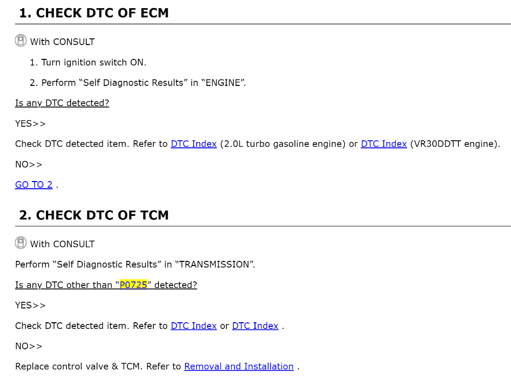
Also, about P0325, are you sure that's the code you got? Because service information says that code doesn't exist for this vehicle. Maybe it was P0335?
Please Log in or Create an account to join the conversation.
- Lvumlow
-
Topic Author
- Offline
- Junior Member
-
- Posts: 20
- Thank you received: 1
You are correct, I typo'd the code. All my problems started with a P0365-00 (camshaft position sensor - bank 1). The local shop replaced the sensor but the code remained. They referrenced a series of com errors and referred me to the dealer. The dealer replaced the bank 1 cam sprocket but that didnt fix the issue. They then replaced the ECU and that didnt fix it either and after about 6 weeks they decided they would no longer work on the car unless I returned the car to stock. This is where I figured I might as well get to know my car so I procured some diagnostic tools and started my troubleshooting. My real problem that this is all new to me and I dont really have any form of guidance or experience to draw from so it is difficult for me to confirm I am on the right track...
I have (or actually had) and Ecutek programmer on the car with a dyno tune from AMS at their facility in Chicago (but this was all wiped when the dealer replaced the ECU) and I remembered it had some logging features so I contacted them and they sent me a diag flash to install and collect logs. I was able to reproduce the P0365 code until I flashed the (new) ECU and that is when I started getting the P0725 code. I got the same reference as you in terms of communication issues between the ECU and the TCM.
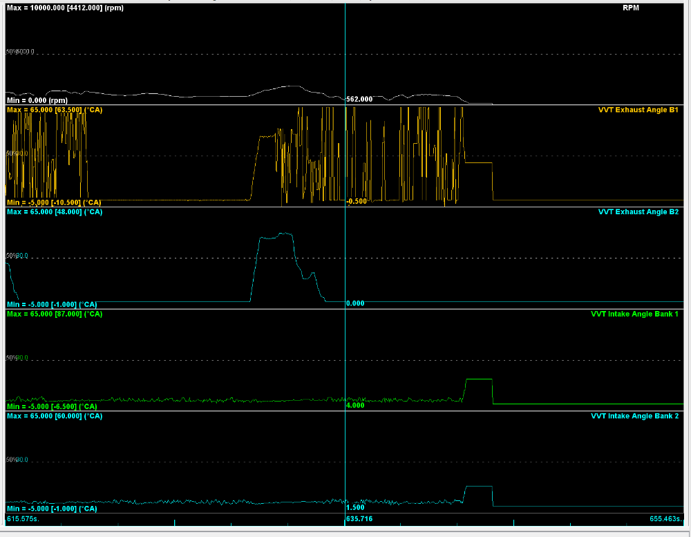
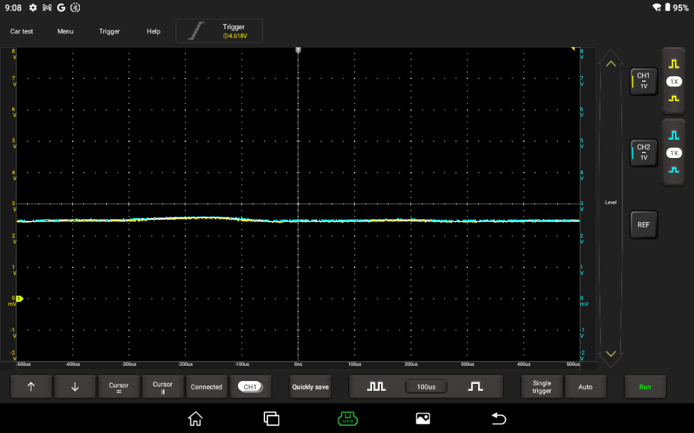
The original P0365 code persisted even after swapping the bank 1 and bank 2 exhaust camshaft position sensors so I figured I must have some type of wiring issue. I have attached a screenshot from the Ecutek logs - you can see very erratic behavior on the bank 1 exhaust VVT so I decided to get a scope hooked up and when I check the CAN bus on PINs 6/14 from a BOB from the DLC, I am seeing both CAN+ and CAN- are at a solid 2.5v so now I am wondering if there is some type of gateway in the way of my testing or possibly both my high and low lines are shorted together? I have included a screenshot for that as well.
At this point, all I can think of is to start unplugging modules to see if I can get the CAN circuits to show a normal wave form?
...without finding someone who is equipped for this type of complex issue, i am pretty much stuck working through this myself and I will stay with it but wish i had more experience as it is difficult to determine if any of my data is accurate.
Any help or guidance would be greatly appreciated...
Kevin Bentley
lvumlow@yahoo.com
(714) 417-6245
Please Log in or Create an account to join the conversation.
- Tyler
-
- Offline
- Moderator
-
- Full time HACK since 2012
- Posts: 6126
- Thank you received: 1542
so I decided to get a scope hooked up and when I check the CAN bus on PINs 6/14 from a BOB from the DLC, I am seeing both CAN+ and CAN- are at a solid 2.5v so now I am wondering if there is some type of gateway in the way of my testing or possibly both my high and low lines are shorted together?
Good thinking!
So, unless you have something hooked up to the DLC that's actively communicating, you're going to see flatlined CAN voltages.
I got the same reference as you in terms of communication issues between the ECU and the TCM.
See, I'm not sure that it is a communication code. :huh: Or at least, I wouldn't treat it like one. You don't have any U01XX or U1XXX codes anywhere, right? Because those are the codes I'd expect to see if you had a true CAN problem. I don't believe the P0725 is highlighting a CAN problem, just that the TCM didn't like the engine speed signal it received.
I was able to reproduce the P0365 code until I flashed the (new) ECU and that is when I started getting the P0725 code.
Not to be nitpicky, but I'd like to be clear on this. P0725 does reset eventually if you clear it, right? Does it take about 100 miles like before? Does the VDC light come on and the engine go into limp mode when P0725 sets?
I have attached a screenshot from the Ecutek logs - you can see very erratic behavior on the bank 1 exhaust VVT
You're not kidding, that IS pretty erratic. :ohmy: Did that same log happen to catch the duty cycle control % for both exhaust cams? I'd be interested to see what the ECM's reaction was during the erratic cam timing behavior.
Please Log in or Create an account to join the conversation.
- Lvumlow
-
Topic Author
- Offline
- Junior Member
-
- Posts: 20
- Thank you received: 1
Please excuse me if it sounds like i am all over the place but I am trying to be open to any an all potential contributing factors as this is an illusive issue.
note: One of the early steps I did when I got the car back from the dealer was swap the exhaust camshaft position sensors from bank 1 to bank 2 to see if the fault would move to the other side. The fault did not appear to move so I figured I have a wiring issue.
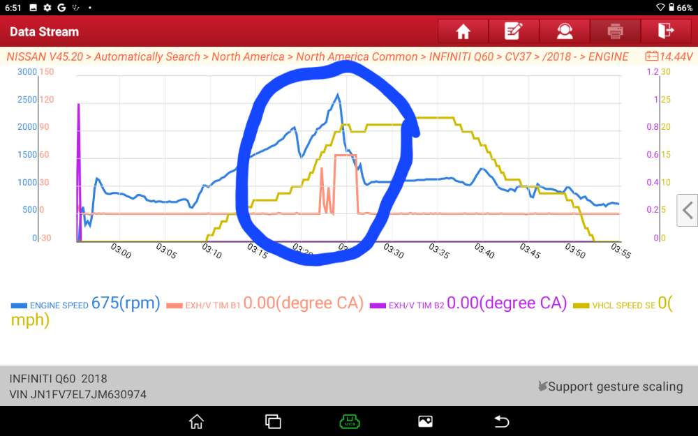
Well, last night I resumed working on the car and since I had an aftermarket infotainment system I decided to return that to stock (the dealer did not like that I had a different unit in there). After replacing the OEM infotainment system it was time to start testing again so I hooked up my scanner and monitored some PIDs while driving. If you have been following this from the beginning, the car never died before. It simply went into limp mode and had a code for the exhaust camshaft position sensor on bank 1. After having two shops work on the car, now the car dies. Well, after testing last night I noticed some interesting things in my scanner capture. See the images below (notice the spike from Bank 2 at the beginning of the capture and I circled where the car started cutting out and wanting to die along with the mis-alignment for both VVT banks throughout the capture.
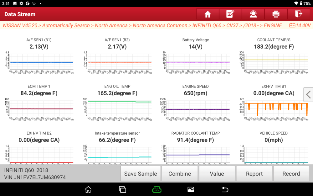
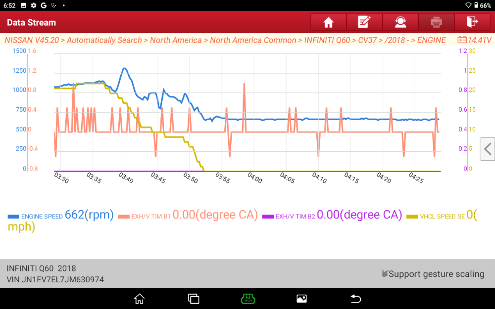
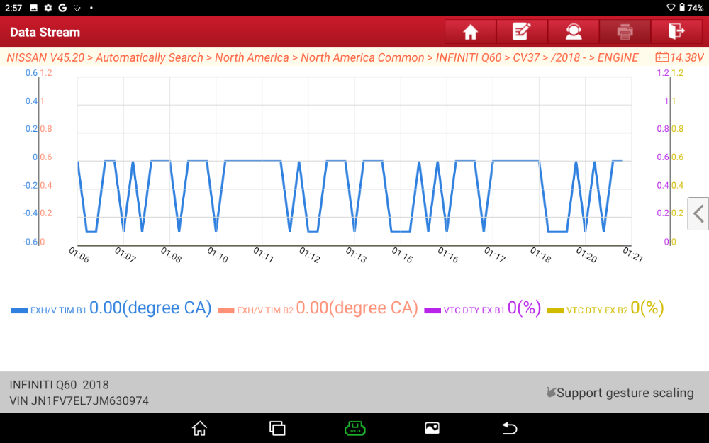
Here are some more captures during my session; if I drive the car it seems the two VVT banks are similar but if I stop the car and let the scale adjust to more detail I can start to see artifacts which look like noise or signal anomalies... Please note that these images are from multiple sessions so the color index for bank 1 may be different in each image so refer to the legend at the bottom to be sure.
So, now here is my current conclusion and it may be a stretch but I am trying to be open minded...
When the problem first started, I the car was going into limp mode with a camshaft position error on bank 1. Carvana's extended warranty force me to go to a small local shop and I am concerned that they may have put a cheap sensor in as a replacement (why would they spend money on an OEM if they can get a cheap on at the local parts store?). At the same time I believe I may have a circuit problem (either with the power or ground as indicated by the hash on the scan data) so the problem remained. The car was sent to the dealer where they threw parts at it (cam shaft sprocket and ECU) but could not fix the problem.
When I got the car home I was frustrated and swapped the sensors from bank 1 to bank 2 to see if the problem would move. It didn't (possibly because I still have a circuit problem on the bank 1 side) but now that I moved the sensors (suggesting one of two possibilities; either the circuit problem fried the replaced sensor or the replaced sensor was a cheap one) I am getting a failure on both sides resulting the car dying and engine speed circuit error? Seem like a stretch? I don't know but the car never died before and I know that when we have multiple sensors, the redundancy can result in a code as opposed to the car dying because it still has other sensors to rely on. With my current theory, now I have a bad circuit problem on one side (bank 1) and I moved the replaced sensor (assuming it was a garbage sensor) to the other side so I may be getting a failure on both sides resulting in the car dying and engine speed circuit messages? Or, the replacement sensor could be getting damaged from any potential noise in the power or ground circuit on bank 1. The other possibility I am considering is that both camshaft position sensors may share a power or ground source?
Please Log in or Create an account to join the conversation.
- Lvumlow
-
Topic Author
- Offline
- Junior Member
-
- Posts: 20
- Thank you received: 1
Please Log in or Create an account to join the conversation.
- Lvumlow
-
Topic Author
- Offline
- Junior Member
-
- Posts: 20
- Thank you received: 1
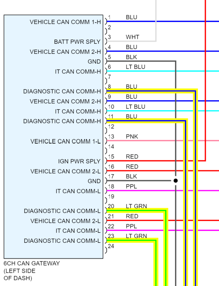
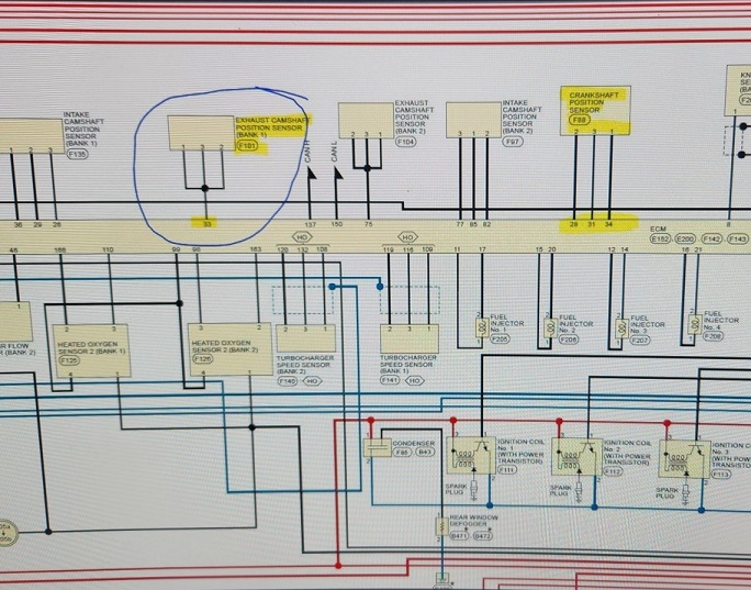
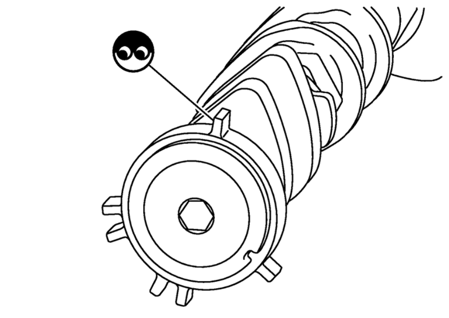
I did try to dig into the schematics and it looks like there is a joint connector in the engine control harness (maybe I am reading this wrong?)
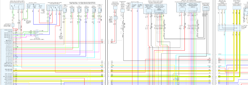
I am not sure how to find that junction but it seems like a good place to start...
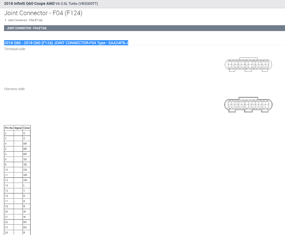
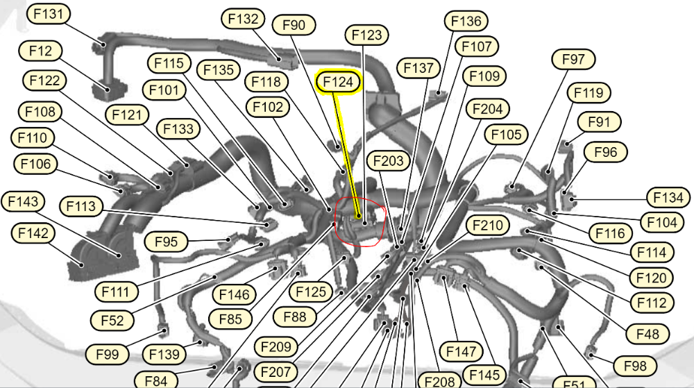
It seems like I am going to have my hands full trying to locate this let alone test it if it does indeed sit within the harness. Anyone have any thoughts?
Please Log in or Create an account to join the conversation.
- Chad
-

- Offline
- Moderator
-
- I am not a parts changer.
- Posts: 2196
- Thank you received: 738
"Knowledge is a weapon. Arm yourself, well, before going to do battle."
"Understanding a question is half an answer."
I have learned more by being wrong, than I have by being right.
Please Log in or Create an account to join the conversation.
- Lvumlow
-
Topic Author
- Offline
- Junior Member
-
- Posts: 20
- Thank you received: 1
This is a brand new sensor (and it was replaced by the first shop to work on it so I feel like I can eliminate the sensor). The ECU was replaced so we can rule that out as well...
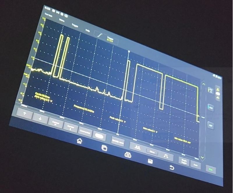
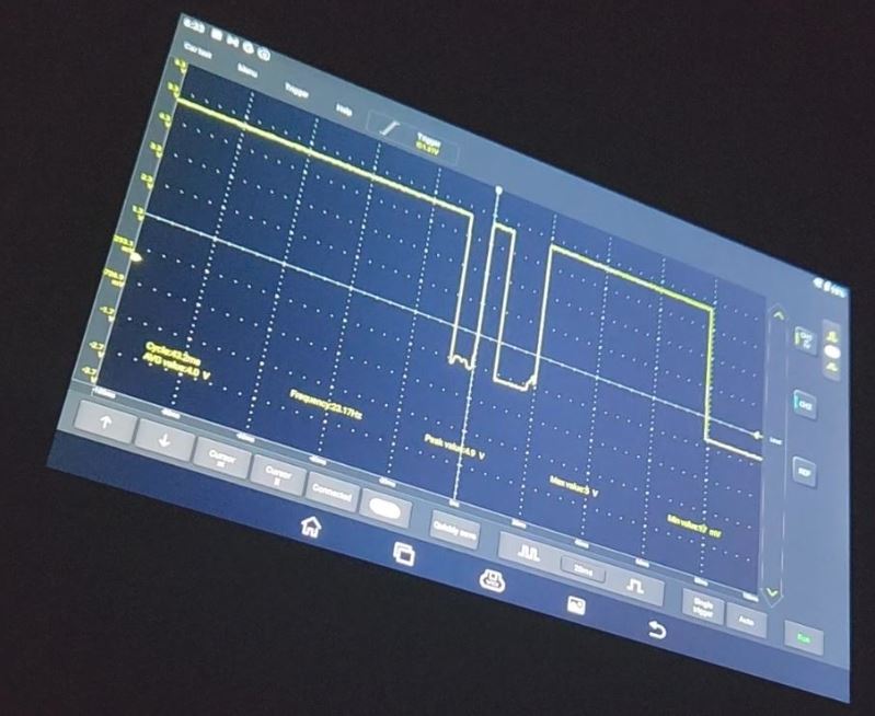
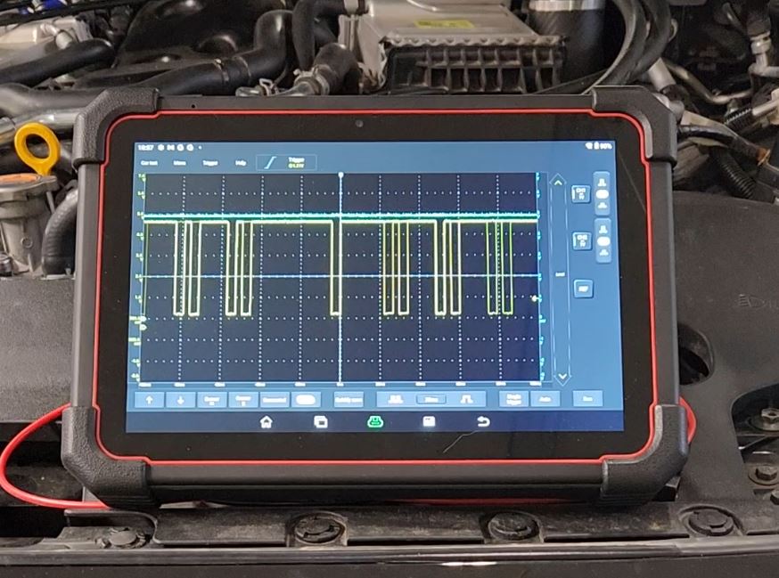
Here is a scope of the sensor @ idle (signal appears to look good?)
...as I start to drive the car and put a load on it, you can see the signal start to degrade progressively.
I have found myself in quite the pickle here; my primary warranty with Infiniti is expired but the powertrain is still under warranty. Infiniti will not continue troubleshooting unless I return the car to factory spec - BUT, even if I do this if this turns out to be a defect in the wiring harness it will not be covered anyway. I have an extended warranty with Carvana but it is unknown if they will honor it ...and if they will, the work still needs to be done by Infiniti which means I have to remove the Heat Exchanger, exhaust, intakes and blow-off valves.
I feel like the only real solution is for me to tear everything apart and and fix the connection problem myself (or possibly add my own wiring?). I inquired about a replacement harness and I was told it would be around $4k (not to mention all the labor involved with tearing the motor down to replace it). There just seems to be no good answer here. The car is valued @ $45k and I cant sell it and I cant repair it so I just don't know where to turn. I cant find anyone who has the skills to assist.
I would like to use some type of voltage drop test to verify the troubled connections but not sure how to safely load the circuits? Anyone have an idea?
I would need a valid voltage drop test for the power line, signal return and ground and how can I load the circuits to get a good reading? Also, it looks like the circuits are shared with the intake sensors at a joint connector so that complicates things as well.
sooooo frustrated but I will just have to keep driving towards a solution so thanks for any guidance or feedback.
Do you think I still should get a capture of the crank position sensor or does this new data mitigate that need?
Please Log in or Create an account to join the conversation.
- Chad
-
- Offline
- Moderator
-
- I am not a parts changer.
- Posts: 2196
- Thank you received: 738
"Knowledge is a weapon. Arm yourself, well, before going to do battle."
"Understanding a question is half an answer."
I have learned more by being wrong, than I have by being right.
Please Log in or Create an account to join the conversation.
- Lvumlow
-
Topic Author
- Offline
- Junior Member
-
- Posts: 20
- Thank you received: 1
I am out of town but will be back tomorrow and will get a waveform for the crank sensor.
I picked up one of Sullivans load probes, do you think there is a safe way to use that on the sensor circuits? I am concerned about the joint connector where the circuit is shared with the intake sensors.
I am not experienced with capturing waveforms but from my camshaft images, it looks like the circuit is pulling to the ground so I am assuming my issue will be on the ground side. Would love to hear what everyone thinks? One of my problems is the car will idle fine (I even put it on jackstands and drove it a couple of miles) but it won't start acting up until I drive it; then I get stuck on the road and it won't start.
I need to be careful not to get stuck somewhere inconvenient.
I did ask the dealer if they can give me some kind of break on the F harness (assuming it turns out to be that) and they said the best price they can give me is $2800 so I am hoping I can find the problem and repair it.
I will follow-up with the crankshaft waveform tomorrow evening when I return home.
Thanks so much for everyone's feedback and help.
Please Log in or Create an account to join the conversation.
- Tyler
-
- Offline
- Moderator
-
- Full time HACK since 2012
- Posts: 6126
- Thank you received: 1542
How many channels does your scope have available? If possible, it'd be best to have all three wires at the cam sensor up on the scope while you get it to act up again. If the drops in the signal correspond with a change in the sensor power or ground, then we can chase those. If the drops occur and the sensor power or ground don't change, then we scratch those off the list of suspects.
The Load Pro is fine, but I'd say wait on getting it out until you scope the sensor power/ground. If you see a power/ground problem, then consider loading the circuits. If you don't see a problem, then the Load Pro won't really help.
The fact that you have to drive it to make the problem happen makes me think about an intermittent short to ground. :huh: A harness that's just rubbed through the conduit and starting to kiss ground somewhere. DON'T go shaking your harness just yet.
Please Log in or Create an account to join the conversation.
- Lvumlow
-
Topic Author
- Offline
- Junior Member
-
- Posts: 20
- Thank you received: 1
Ok, I have some updates..
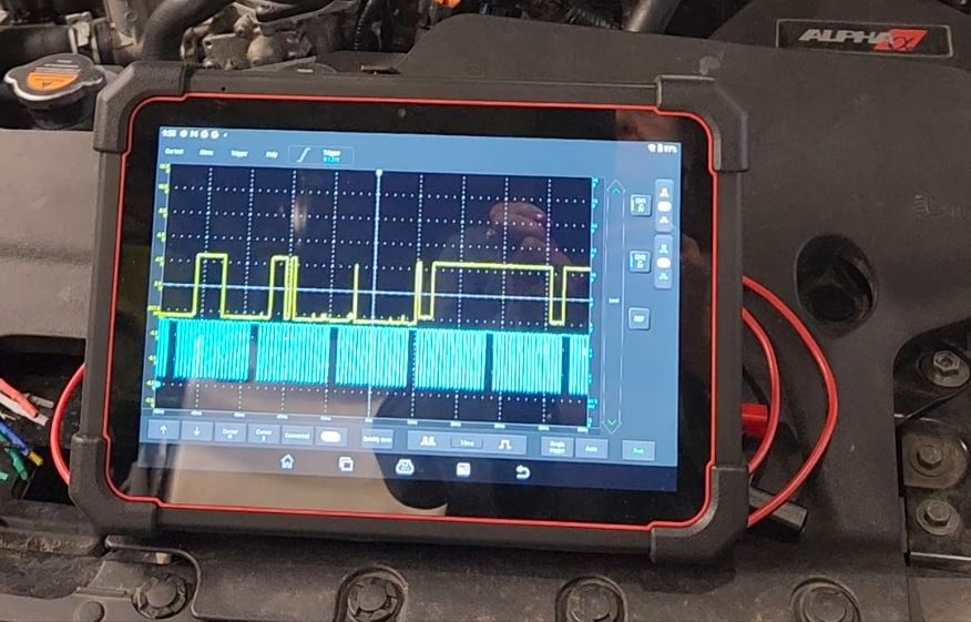
Here are some waveform captures with the exh. camshaft position sensor and the crankshaft position sensor. I was lucky to capture the failure. I don't see any interruption from the crankshaft sensor.
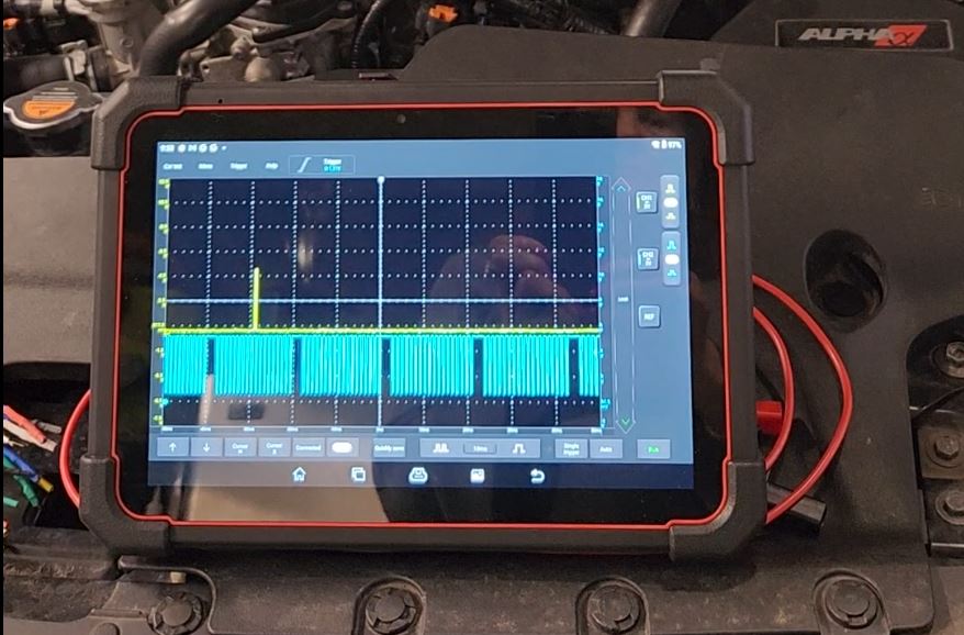
Unfortunately, I only have a 2 channel osciliscope so I have to test in batches (wish I could afford a better unit)
Here are some waveforms of the camshaft and feed circuit and again I was lucky to capture the failure...
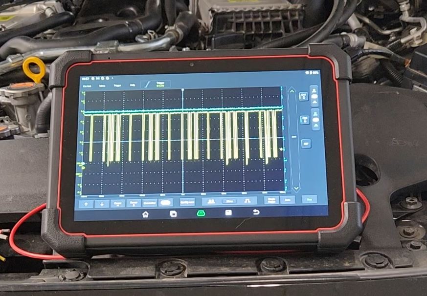
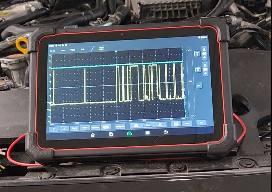
We see the same degradation of the signal from the cam sensor but don't see anything on the feed circuit. I am not sure how to load the ground but I used the circuit ground for the feed.
Ok, now I turned to testing the cam circuits. I disconnected the ECU and the sensor and applied 12v to the sensor end and used a load pro on the harness side of the ECU connection and applied the .5amp load from the load pro. Saw no open, short or high resistance in both the signal and feed circuit.
I did however discover some disturbing things in the harness once I started to unwrap it to find my wires...
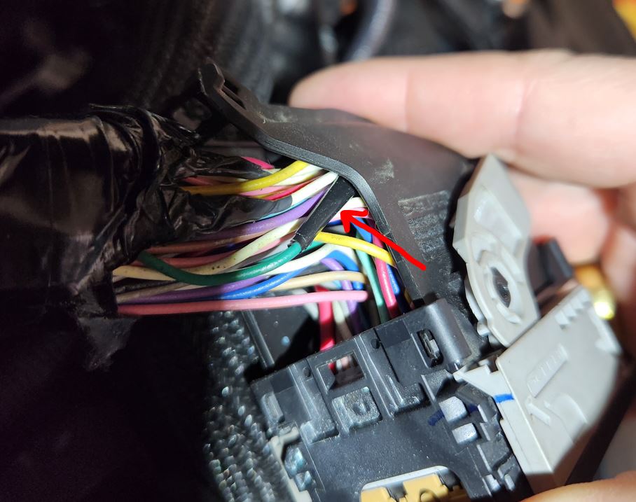
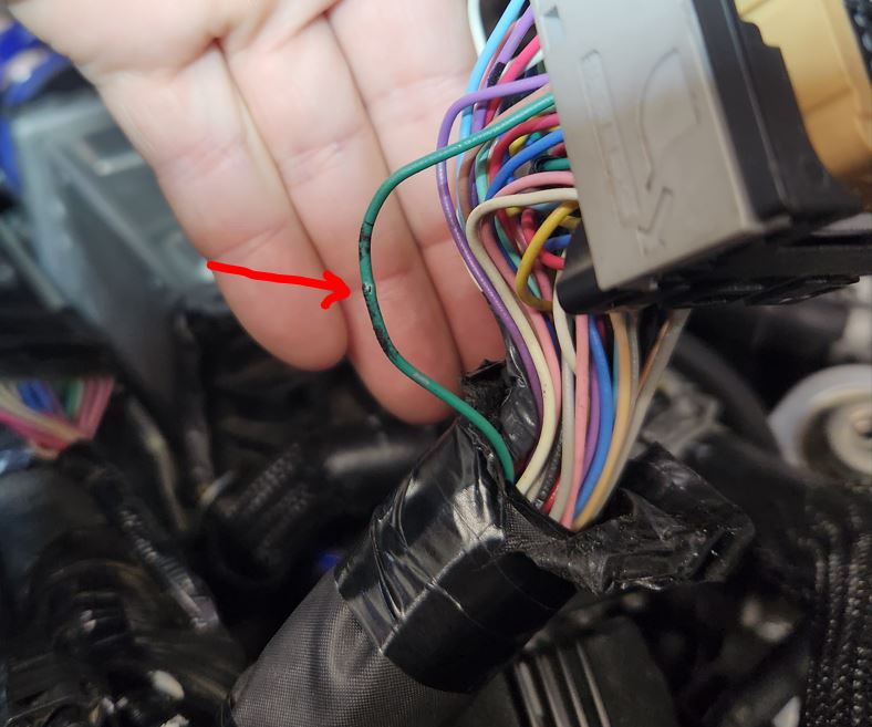
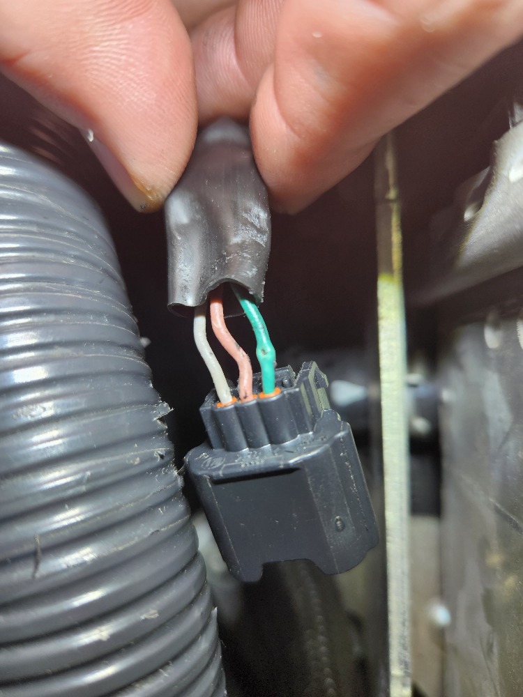
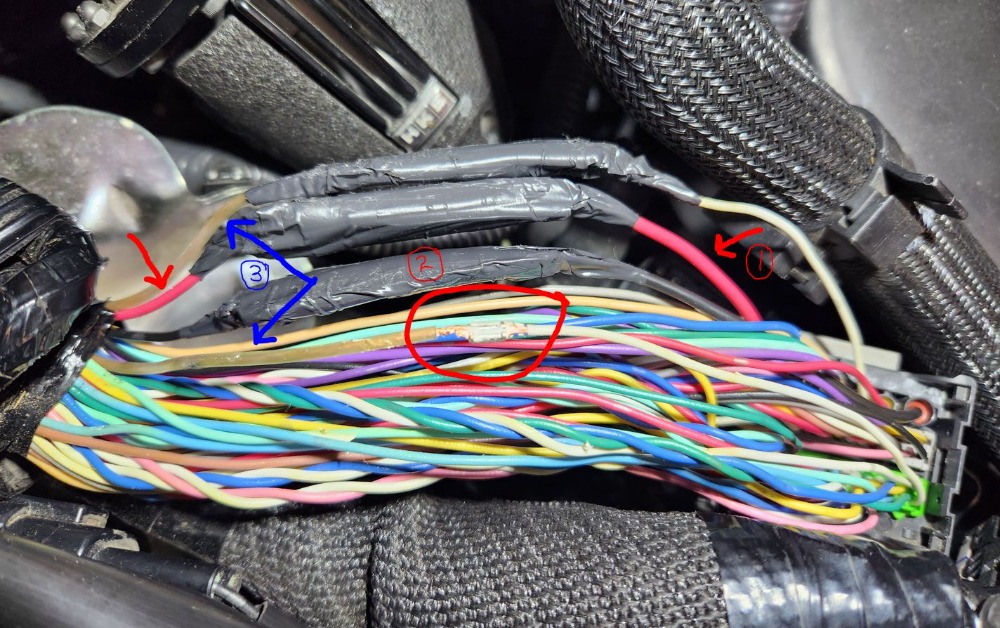
Yes, that is speaker wire! Someone was inside this harness previously. I don't think the dealer did this and the lines that are repaired deal with the high pressure fuel pump (red & black - notice they used smaller gauge wires) and both bank knock sensors (white wires with the speaker wire). I don't think this is related to the problem but it shows me that someone has been in the harness before. Hard for me to imagine since I have had the car since it had 9k miles so that work must have been done pretty early in the cars history. I do however believe the dealer poked the huge holes in the cam signal line though. I use a phils probe and it barely makes a hole which I always seal with nail polish but it hurt my OCD to see these damaged lines ...and they all passed my voltage drop tests so I will seal them up.
Well, that's it for me. Anyone have any ideas?
Please Log in or Create an account to join the conversation.
- Tyler
-
- Offline
- Moderator
-
- Full time HACK since 2012
- Posts: 6126
- Thank you received: 1542
I'll grab a couple of your shots and try to explain my line of thinking at the moment. Hopefully others will weigh in with their thoughts as well.
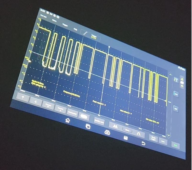
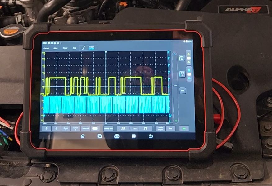
I'm taking this shot as part of the problem. I can't find any known good captures for this engine.
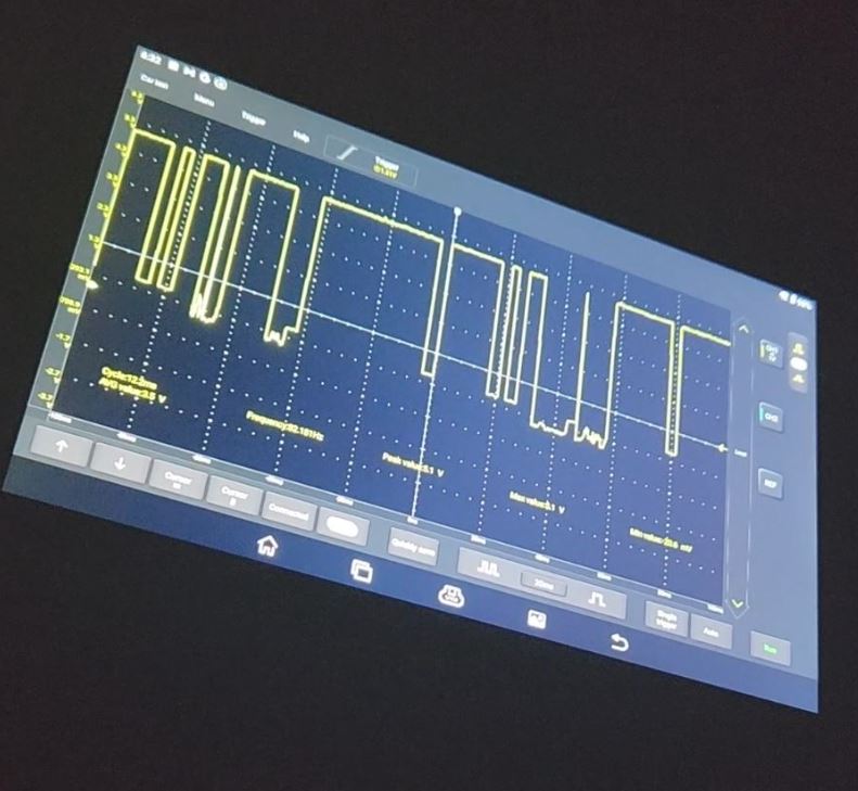
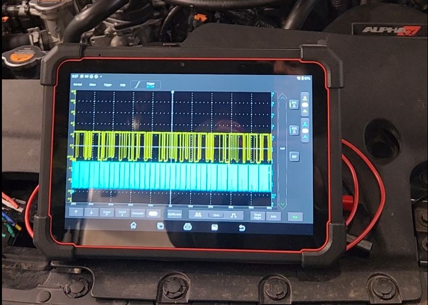
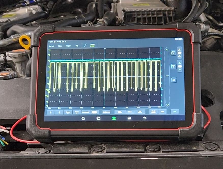
I'm taking this as working correctly. Nissan has used there 1-1-2-2 camshaft pattern for awhile, and yours fits that. They even have an example of this in SI:
There's a little bit of a refresh rate problem going on in this shot, but so what, the basic waveform is there.
In the theoretical known good, the pulses are clean but don't necessarily pull all the way to ground. :huh: But in the theoretical problem shot, the signal is stuck all the way at ground. I don't know if that has to do with the nature of the problem, or if that has something to do with using the sensor signal circuit as the scope ground. Just thought that was interesting to note.
Your cam signal/sensor power waveform has me pretty convinced it's not a sensor power/ground problem. I *think* that if the sensor ground was a problem, you'd have lost both signals. If sensor power was a problem, it'd have shown up. Again, if others have thoughts, I'd love to hear them.
For me, that leaves two suspects. An intermittent open in the signal wire (which would result in 0V at the sensor) and an intermittent short (which would also result in 0V at the sensor). Given the harness shenanigans you found, both are possible. :lol:
Your OCD may not like my suggestion but... Your next best move may be to install a temporary signal circuit overlay. As in, cut the cam signal wire at the sensor and at the ECM, both in easily repairable locations. Connect up your own wire in between. The connections don't have to be art, and the routing doesn't have to be perfect.
If your sensor waveform cleans up, then the problem was somewhere in the signal wire. From there, you can consider your repair options. If nothing changes, curse my name a few times while you fix the wire and continue your testing.
The only other thing I can think of would be a spread pin at the ECM connector itself. Speaker wire installer could have been front probing the connector pins with a steak knife or something. :huh: If you have anything to test terminal tension, you could check the cam signal pin against others in the same connector.
Man I hope all that junk made sense. :blink:
Please Log in or Create an account to join the conversation.
- Chad
-
- Offline
- Moderator
-
- I am not a parts changer.
- Posts: 2196
- Thank you received: 738
I am not sure how to load the ground
Simply, connect your second Scope channel to the Ground Circuit. You would expect to see 0 volts. 100mv, or less, is good. Try to recapture the cam signal fault. The voltage on the ground circuit should remain 100mv, or less. Any voltage activity is an indication of a bad ground.
With the sensor Power and Ground being verified as good, I would try one more scope test before overlaying a wire, as Tyler suggested. Put one scope channel on the signal wire, at the sensor. Put the other scope channel on the signal wire at the PCM. Try to capture the fault, again. If the signal wire has an intermittent OPEN, the voltage will be 5 volts at the PCM, but 0 volts at the sensor. If the signal wire has an intermittent short to ground. Both scope channels will drop to zero.
"Knowledge is a weapon. Arm yourself, well, before going to do battle."
"Understanding a question is half an answer."
I have learned more by being wrong, than I have by being right.
Please Log in or Create an account to join the conversation.
- Lvumlow
-
Topic Author
- Offline
- Junior Member
-
- Posts: 20
- Thank you received: 1
I love the idea of scoping both ends of that line but I am scarred by all the times I have been left stuck on the side of the road.
I decided to go with the overlay strategy so I installed a temporary exhaust camshaft signal line and cleaned up the other repair I unwrapped.
Buttoned everything up and have been strategically widening my circle of test drives. So far, I have 20 miles with no issues or codes. Fingers crossed.
I find it incredible that literally anyone can get the right tools and find helpful resources like this to diagnose and repair this themselves. When the dealer gave up on this, I was more than concerned. I'm still tossing around what to do about a permanent fix for the harness, given the previous repairs it may be prudent to just take the hit and replace it. I tend to keep my cars forever. Still have my 2004 G35 with an APR widebody kit and love it (i would love to widebody this car...].
I guess I will be in evaluation mode for a little while but will check back with updates.
Thanks again for all the feedback and help. I felt like everyone gave up on me and I was left holding the bag but this site really helped me attack this on my own.
I am going to take it for a 100 mile trip tonight but will be sure to take my AAA card, lol.
... high five to scanner danners videos; I learned so much. Hope there is something in this case study that will help others. I can't imagine I am the only one with this issue.
Please Log in or Create an account to join the conversation.
- Tyler
-
- Offline
- Moderator
-
- Full time HACK since 2012
- Posts: 6126
- Thank you received: 1542
I love the idea of scoping both ends of that line but I am scarred by all the times I have been left stuck on the side of the road.
Understandable. But I'm still glad Chad suggested it, as it's a much less invasive test than what I suggested. :blush:
I decided to go with the overlay strategy so I installed a temporary exhaust camshaft signal line and cleaned up the other repair I unwrapped.
Buttoned everything up and have been strategically widening my circle of test drives. So far, I have 20 miles with no issues or codes. Fingers crossed.
...
Going to take it for a 100 mile trip tonight but will be sure to take my AAA card, lol.
Great to hear! Hopefully you won't need the AAA card. I'll be watching for a follow up.
Please Log in or Create an account to join the conversation.
- Lvumlow
-
Topic Author
- Offline
- Junior Member
-
- Posts: 20
- Thank you received: 1
I am happy to report that I believe we can call this issue fixed. The car has over 450 miles on it without a hiccup. I have seen the car go this long before but it was at the beginning of the issue and I have seen a frequency increase over time so I think we are good.
In conclusion, there are a few things I learned along the way that might help others.
DTC codes are not always what they seem! If you have been following this case you will notice that we had a series of codes along the way so be careful to start chasing codes until you can verify your diag methodology.
It didn't help that I had other teams working on this car before i got it but this appears to be a basic friction short in the main harness (on the bank 1 exhaust camshaft signal circuit). If you look at some of the early logs, they were collected using the Ecutek logging features and the later logs were from a scanner and finally the osciliscope captures that I completed. All were accurate but I think this is a great example of the value of a scope. The first two shops missed this diagnosis and I speculate this could be related to the data they were using to diagnose the issue?
Over $15k has been spent trying to fix this issue (taking 3 months to solve) and ultimately it was less than $2 in parts and about 20 minutes to fix the problem. I am new to this but I have heard many reports of similar stories. Just imagine how much money gets spent on mis-diagnoses? The dealer replaced the exh camshaft position sensor, replaced the camshaft sprocket (actually pulled the motor to change this...) and even replaced the ECU ...all with no luck. I find it a little ironic in that when I first dropped the car off at the dealer I sent them a link to another forum post where another Q60 user had similar issues and it was ultimately the F harness. The dealer looked at that and decided this was not related to that condition. I wonder if Inifiniti knows they could have saved $10k if they could have vetted that suggestion? I want to be fair, it is very easy to arm-chair QB this and it was a difficult condition to troubleshoot but you would think all the master techs they had working on the car should have used a better method to diagnose the car rather than just throwing parts at it like they did. It also frustrated me that they went that far only to give up on it. I believe they simply used the cars modifications as a convenient excuse to get the car out of the shop. Forcing me to restore a factory heat exchanger or intakes and exhaust was just common sense that they had nothing to do with the fault. Oh well, I digress...
If you look through some of the early data, it is clear how much more resolution you get from a scope so if you have been on the fence about getting one this may help your decision. I simply would not have been able to fix this without the help of the oscilloscope. My only regret is getting a 2 channel scope, if you are going to get one just pull the trigger and get at least a 4 channel.
Thank you so much for all the help. Scannerdanner's videos and this forum were very helpful so the tools and tips are out there if someone is willing to do their homework.
I personally know of at least one other 2018 red sport with this issue (damage in the F harness) so this may come up in a search in the future. Going by the early harness work on this car, it seems plausible that this car had issues very early on in its life. It is possible Infiniti had some type of production problem or something?
The real challenge is that the problem circuit passed all the conventional tests; continuity, open, short and high resistance. The erratic signal caused all sorts of havoc with the computer. I was getting transmission codes, camshaft position sensor errors for both banks, etc... just totally confusing if you think linearly and start chasing codes.
My best advice is to never give up and search for ways to include or exclude possibilities until you zero in on the problem. Sometimes, issues like this may need to persist until they get more frequent so it will be easier to locate. In the early phases of this incident, it was quite challenging because the breach in the wire may have been new and very small (only occurring every 100 miles or so) , but over time it became more frequent, enough so to assist in getting a scope capture of the fault.
Best of luck to anyone fighting something like this, I know I am very happy to put this one behind me, lol
Please Log in or Create an account to join the conversation.
- Tyler
-
- Offline
- Moderator
-
- Full time HACK since 2012
- Posts: 6126
- Thank you received: 1542
So, now that you're satisfied that you're facing a wiring problem, have you decided how to go about fixing it? New harness? Make the repairs yourself?
Please Log in or Create an account to join the conversation.
- Lvumlow
-
Topic Author
- Offline
- Junior Member
-
- Posts: 20
- Thank you received: 1
Given the previous wiring repairs in the harness, I would spend the money and replace the whole thing but I did incur some expense working through this so I am going to give it some time and make a decision down the road. If I experience any more issues I will default to replacing the harness.
Now, I feel much better armed to identify and work through a similar issue in the future. It is interesting to look back at the whole process with the 20/20 hindsight perspective. I hope it helps someone down the road with similar symptoms.
I utilized many different resources trying to get up to speed on this and I have to admit that everything in Dan Sullivans book was right on the money. Clearly, Scanner Danners training was very helpful also so I hope everyone new realizes that there are tons of great resources available.
Keep up the great work guys, you were very helpful. AMS was very helpful also. The Ecutek logging features were also instrumental in keeping me on the right track.
Please Log in or Create an account to join the conversation.