Help us help you. By posting the year, make, model and engine near the beginning of your help request, followed by the symptoms (no start, high idle, misfire etc.) Along with any prevalent Diagnostic Trouble Codes, aka DTCs, other forum members will be able to help you get to a solution more quickly and easily!
*solved* 08 Avalanche P0446 FTP sensor circuit. Pcm or mixed grounds?
- RPMsAutoServices
-
 Topic Author
- Offline
- New Member
-

Less
More
- Posts: 3
- Thank you received: 1
2 years 11 months ago - 2 years 11 months ago #61026
by RPMsAutoServices
*solved* 08 Avalanche P0446 FTP sensor circuit. Pcm or mixed grounds? was created by RPMsAutoServices
I've got a real interesting one. 08 awd Avalanche 5.3 Vin 3 with P0446. FTP sensor reporting 0.55V when removed from tank. 5V supplied to sensor. It's a new AC DELCO sensor but it reads the same as the original bosch. I tried 3x sensors from autozone and advance auto in their own repackaged brands and they reported a full 5V (more vacuum than in space). The ac Delco and bosch ohm out to 5k from signal to ground, the other 3 were 50 ohms and clearly not manufactured to spec. But that's not where it gets interesting. With key off I get less than 2 ohms to low ref at the sensor but koeo it is 80 ohms. If I start the car it drops to 0 Ohms. None of which affects the reported 0.55V from the sensor. I verified an actual 0.57V at the signal wire. I suspect that the sensor was never the problem and that the pcm is shorting the signal to ground internally, thus shunting the voltage. I will pull the wire from the pcm and remeter the voltage tomorrow. The strange behavior of the low ref resistance to battery negative is still bothering me tho. It only has a potential of 20-40mV but it really seems like something is back feeding through the system. Maybe something else shorting to ground or finding an incorrect ground path. The same 80 ohms previously mentioned does occur at the ground wire going into the pcm so I don't think the problem is isolated to the FTP sensor circuit. And there have been similar behaviors reported when an aftermarket fuel pump connector incorrectly instructs techs to install the ground for the pump inverted with the ground for the sending unit and ftp sensor. It tested exactly the same with the fuel pump connector removed, which appears to be OEM anyway. I'm wondering if there's a bad ground on the engine or short to ground on some other sensor. I scanned all systems on the vehicle and I was getting communication errors for the abs module but I cleaned the ground up for it and those went away without helping one bit. So it's either an internally shorted pcm or something is back feeding through the wrong ground somewhere. I did forget to ohm signal wire to ground... I'll check that tomorrow as well. I'm about stumped. Anyway I hope I explained this well enough because it seems like it's a very interesting case!
Last edit: 2 years 11 months ago by RPMsAutoServices. Reason: Solved
Please Log in or Create an account to join the conversation.
- George Uk
-
- Offline
- Junior Member
-

Less
More
- Posts: 32
- Thank you received: 6
2 years 11 months ago - 2 years 11 months ago #61029
by George Uk
Replied by George Uk on topic 08 Avalanche P0446 FTP sensor circuit. Pcm or mixed grounds?
Is this a 3 wire Sensor ? 5v, Ground & Signal ?
If it is then can you get ANY diagnostic value from resistance measurements across its pins ?? Open or Short may be but anything conclusive ?
Can you apply Pressure & Vacuum to the sensor, whilst plugged in to get independent verification of its accuracy using Voltage on the Signal Wire and Live Data PID ??
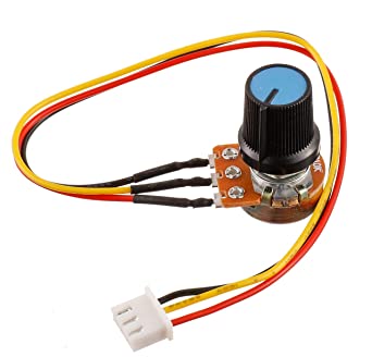
A three wire Variable potentiometer to emulate the sensor would guide you too.
If it is then can you get ANY diagnostic value from resistance measurements across its pins ?? Open or Short may be but anything conclusive ?
Can you apply Pressure & Vacuum to the sensor, whilst plugged in to get independent verification of its accuracy using Voltage on the Signal Wire and Live Data PID ??
A three wire Variable potentiometer to emulate the sensor would guide you too.
Last edit: 2 years 11 months ago by George Uk.
Please Log in or Create an account to join the conversation.
- RPMsAutoServices
-
Topic Author
- Offline
- New Member
-
Less
More
- Posts: 3
- Thank you received: 1
2 years 11 months ago - 2 years 11 months ago #61031
by RPMsAutoServices
Replied by RPMsAutoServices on topic 08 Avalanche P0446 FTP sensor circuit. Pcm or mixed grounds?
Yes that's the jist of it. 5V ref, signal, low ref. Variable resistance based on deflection of what I assume is a piezo element or something.
And having the sensor out of the tank exposed to atmospheric pressure should return a value in the range of 1.3-1.7V but I'm getting 0.55V. And that is true of the original sensor and the ac Delco. And after getting 3 bad sensors from advance and autozone, the odds of a different brand coincidentally being defective to the exact same specs as the original sensor seems highly unlikely. I have another ac Delco coming in today and if that returns 0.55V then the best I can surmise is high resistance on the signal wire (would have to be in the neighborhood of 5k ohms), a bad ground somewhere else causing some sort of destructive interference as if the sensor is being run in parallel with another resistance and splitting the current, or an internal pcm short of the signal or 5v ref circuit to another sensor, etc. Or idk what else.
I'm thinking about ohms law here and I do get a full 5V ref at the sensor and the resistance is 5k from 5v ref to signal and 5k ohms from signal to low ref. So it's dropping 0.55V x2 = 1.1V across 10k ohms. That works out to an extra 35k ohms added to the series of the circuit. I just have to find that 35k ohms!
Edit: the 35k ohms could be in the 5v ref wire and still reflect 5v when open.
Last edit: 2 years 11 months ago by RPMsAutoServices. Reason: Thought of something else
Please Log in or Create an account to join the conversation.
- George Uk
-
- Offline
- Junior Member
-
Less
More
- Posts: 32
- Thank you received: 6
2 years 11 months ago #61032
by George Uk
I don't believe you can apply Ohms law to that sensor in that way. Being 5v, Ground & Signal there is likely electronics in there and you are measuring across a circuit board. There may not be any direct correlation between the Resistance and the Output of the sensor
Replied by George Uk on topic 08 Avalanche P0446 FTP sensor circuit. Pcm or mixed grounds?
I'm thinking about ohms law here and I do get a full 5V ref at the sensor and the resistance is 5k from 5v ref to signal and 5k ohms from signal to low ref. So it's dropping 0.55V x2 = 1.1V across 10k ohms. That works out to an extra 35k ohms added to the series of the circuit. I just have to find that 35k ohms!
I don't believe you can apply Ohms law to that sensor in that way. Being 5v, Ground & Signal there is likely electronics in there and you are measuring across a circuit board. There may not be any direct correlation between the Resistance and the Output of the sensor
Please Log in or Create an account to join the conversation.
- RPMsAutoServices
-
Topic Author
- Offline
- New Member
-
Less
More
- Posts: 3
- Thank you received: 1
2 years 11 months ago - 2 years 11 months ago #61034
by RPMsAutoServices
Replied by RPMsAutoServices on topic 08 Avalanche P0446 FTP sensor circuit. Pcm or mixed grounds?
I found the problem.
At some point the FTP sensor was replaced as it was manufactured in 2017 and the vehicle is 2008. It was a bosch sensor, but so was the ac Delco I got in genuine GM packaging.
The pinout was cast into the sensors, and matched the connector pinout on alldata. However, the wires going into the sensor connector were out of order from the sensor and connector diagram listed in alldata. It looked like an oem connector and wiring so I can't for the life of me figure out how the wiring could have ended up being switched, but upon putting them in the correct order the problem was solved. The sensor now reads 1.47V, which is right in the middle of the specified range of 1.3-1.7V!
Last edit: 2 years 11 months ago by RPMsAutoServices. Reason: Typo
The following user(s) said Thank You: Tyler
Please Log in or Create an account to join the conversation.
Time to create page: 0.273 seconds