Help us help you. By posting the year, make, model and engine near the beginning of your help request, followed by the symptoms (no start, high idle, misfire etc.) Along with any prevalent Diagnostic Trouble Codes, aka DTCs, other forum members will be able to help you get to a solution more quickly and easily!
2006 2.2 Malibu -Oscilloscope not as easy answer as I thought
- 3505angels
-
 Topic Author
- Offline
- New Member
-

Less
More
- Posts: 4
- Thank you received: 0
3 years 2 weeks ago #60501
by 3505angels
2006 2.2 Malibu -Oscilloscope not as easy answer as I thought was created by 3505angels
So ive had a stalled car for a while and diagnostics says its a module communication error. BCM and pcm dont communicate. Took some time to learn about can bus and oscilloscopes and finally took a peek and I was hoping the problem would be obvious but it doesnt seem to be erratic readings like what I saw while educating myself. Im at my wits end and if its just a module replacement id rather save myself the 500 dollars of labor a shop would charge. I checked the gm low speed lan and the readings look good. I unplugged modules on and off and readings didnt change. Checked all power and grounds and nothing seems off. Any ideas? Only three modules in the high speed bus. BCM, Steering, and pcm/ecm. Ive yet to check the grounds and 5 volt reference with the oscilloscope but multimeter showed them as fine. I think ill do that maybe the oscilloscope will show a fault there? Any suggestion from an experienced person would be much appreciated.
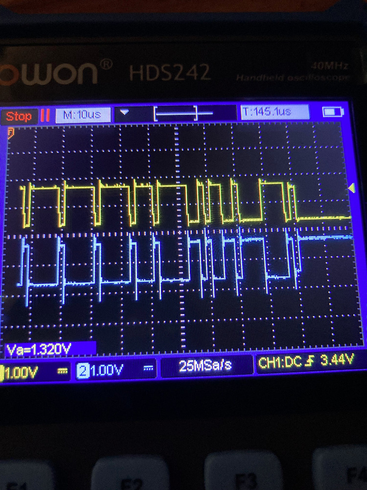
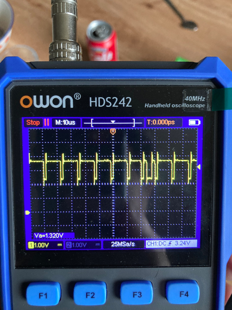
P.s. Do those readings look fine? Im using a 1x probe. Since I have only videos and some posts from google to reference im basing myself off of that and well in those cases its obvious to see something is off but in my results they look fine? Yellow is high speed can +.
P.s. Do those readings look fine? Im using a 1x probe. Since I have only videos and some posts from google to reference im basing myself off of that and well in those cases its obvious to see something is off but in my results they look fine? Yellow is high speed can +.
Please Log in or Create an account to join the conversation.
- 3505angels
-
Topic Author
- Offline
- New Member
-
Less
More
- Posts: 4
- Thank you received: 0
3 years 2 weeks ago #60504
by 3505angels
Replied by 3505angels on topic 2006 2.2 Malibu -Oscilloscope not as easy answer as I thought
Just to not be confusing the readings are high speed can bus yellow is + and blue is -. Just wanted to show how they mirror each other and I think they look fine but if someone says otherwise im curious.
Please Log in or Create an account to join the conversation.
- Matt T
-
- Offline
- Platinum Member
-

Less
More
- Posts: 751
- Thank you received: 276
3 years 2 weeks ago #60506
by Matt T
No EBCM?
Anyways which of the HS-CAN modules can you talk to with a scan tool? And what U codes is each module setting?
Also have you done an ohm check across 6 & 14 at the DLC yet?
Replied by Matt T on topic 2006 2.2 Malibu -Oscilloscope not as easy answer as I thought
Only three modules in the high speed bus. BCM, Steering, and pcm/ecm.
No EBCM?
Anyways which of the HS-CAN modules can you talk to with a scan tool? And what U codes is each module setting?
Also have you done an ohm check across 6 & 14 at the DLC yet?
Please Log in or Create an account to join the conversation.
- 3505angels
-
Topic Author
- Offline
- New Member
-
Less
More
- Posts: 4
- Thank you received: 0
3 years 2 weeks ago #60520
by 3505angels
Replied by 3505angels on topic 2006 2.2 Malibu -Oscilloscope not as easy answer as I thought
Both bcm and pcm accuse each other of no comm. Both are communicable via tech 2 and both give proper readings. Only wrong data is pcm showing fuel disabled which I believe to be from not talking to the bcm and thus not receiving the okay to start (the antitheft key authorization stuff). I had replaced the steering module as it links the 2 but no dice. Car is showing no power steering as well which is why I figured it was the culprit module.
No ebcm hydraulic brakes.
No ebcm hydraulic brakes.
Please Log in or Create an account to join the conversation.
- Cheryl
-
- Offline
- Platinum Member
-
Less
More
- Posts: 1216
- Thank you received: 215
3 years 2 weeks ago #60521
by Cheryl
Replied by Cheryl on topic 2006 2.2 Malibu -Oscilloscope not as easy answer as I thought
I don’t think you can check resistance on the pins at the dlc. I think it goes to the bcm then out of the bcm to the rest of the modules
Please Log in or Create an account to join the conversation.
- 3505angels
-
Topic Author
- Offline
- New Member
-
Less
More
- Posts: 4
- Thank you received: 0
3 years 2 weeks ago #60523
by 3505angels
Replied by 3505angels on topic 2006 2.2 Malibu -Oscilloscope not as easy answer as I thought
The ohm reading were 61.2 between the pins which I think is fine.
These are the codes I am picking up. I erased the codes because several codes popped up when I had unplugged the modules. Upon new codes I saw some new ones that hadnt appeared. Dont know if they are related to a weakening battery. Will need to recharge it to verify.
Pcm
u0141 Lost comms with bcm
Steering
u2109 Lost comms with pcm
u2107 Lost comms with bcm
u2100 Can bus comms malfunction
Bcm
u2111 Lost comms with steering
u210 Lost comms with pcm
New codes: b2555 Short or open in passenger lamp control circuit// Theft deterrent module u2105,u2107,u2100 Lost comms with pcm, bcm and can bus malf.
Please Log in or Create an account to join the conversation.
- MarkBeck101
-
- Offline
- Junior Member
-

Less
More
- Posts: 31
- Thank you received: 2
2 years 11 months ago #60905
by MarkBeck101
Replied by MarkBeck101 on topic 2006 2.2 Malibu -Oscilloscope not as easy answer as I thought
Can you provide a description of all of the buses and how they are related (network tree), for example connected to the DLC or beyond a gate way (BCM?). Many scan tools provide the network topology (tree). Once this is understood then we need to look at a vehicle wiring diagram to see how the CAN bus connections are made. For example, daisy chained through each module or using a network distribution block, and any intermediate connection points like in-line or bulkhead connectors. For modules on the same bus with the termination and connections working the modules on this bus should be able to see each other. To disrupt bus communication there is something preventing the modules from communicating. Many times through the DLC you can talk to one module (the gateway) but not another on an output network. If a bus is corrupted then all modules on the bus will not be able to see each other. The vast majority of communication faults are in the wiring or connectors, with the main causes being harness chaffing or water intrusion. Only in vary unique failures would a module CAN interface IC take down the bus.
Please Log in or Create an account to join the conversation.
Time to create page: 0.320 seconds