2007 Dodge Durango 4X4 4.7 V8 - Trouble Code C1008 Brake Fluid Level Sensor circ
- W8up4Rick
-
 Topic Author
- Offline
- New Member
-

- Been in the Automotive field since 2009.
- Posts: 6
- Thank you received: 5
He has also replaced...... (before bringing it to me)
The brake fluid level sensor.
The master Cylinder with reservoir that included another new fluid level sensor.
The brake booster (had brake fluid in it).
I am not sure what else to test, I was wondering if anyone had experienced this issue or had any advice on where to look next.
Thanks in advance,
Rick
Please Log in or Create an account to join the conversation.
- cheryl hartkorn
-
- Offline
- Platinum Member
-

- Posts: 694
- Thank you received: 130
Please Log in or Create an account to join the conversation.
- W8up4Rick
-
Topic Author
- Offline
- New Member
-
- Been in the Automotive field since 2009.
- Posts: 6
- Thank you received: 5
After doing a little more digging on this system and reaching out to a friend that works at a Chrysler dealership I am finding out that there is another module of some sort in between the FCM and the Instrument cluster. I left the description and operation paper at my work so I can't remember what the Module was called and Alldatapro doesn't even speak of it and doesn't even offer an electrical diagram for it so my info is extremely limited and i am having to depend on a friend to try and use his dealer program to provide me information. But from what i recall it is a module that takes the info from the FCM and tells the instrument cluster to set the brake light on and set a code. The C1008 code is being set in the FCM module not the ABS module.
Please Log in or Create an account to join the conversation.
- Tyler
-

- Offline
- Moderator
-

- Full time HACK since 2012
- Posts: 6124
- Thank you received: 1541
Do you have access to a variable resistor? Mostly, I'm interested to know what voltage on the signal wire will make the FCM happy. 2.5V? Not sure exactly, just a guess.
I found this part at my local Radio Shack , and works perfectly for substitution testing. Try hooking the resistor up, start at 10K ohms (which is about what the level sensor reads anyway) and dial it down until the level PID reads OK. You can also use your multimeter to double check voltage drops, AND that the FCM is seeing the same voltage that you are at the level sensor.
If you can shut the FCM up with a variable resistor, then I'd think that there's still something wrong with the level sensors that have been installed already. Are there part options based on trim packages?
Please Log in or Create an account to join the conversation.
- W8up4Rick
-
Topic Author
- Offline
- New Member
-
- Been in the Automotive field since 2009.
- Posts: 6
- Thank you received: 5
Please Log in or Create an account to join the conversation.
- Tyler
-
- Offline
- Moderator
-
- Full time HACK since 2012
- Posts: 6124
- Thank you received: 1541
W8up4Rick wrote: When I get to work Monday I will post description and operation. I did forget to mention that I did put a resistor in place of the sensor and was able to make the FCM happy and the brake fluid level read normal on my scan tool and codes cleared. That would be my last option as to a "fix" though. I would like to get to the bottom of this and fix it right.
Agreed, wiring a resistor in permanently would be the last resort. But at least we know the FCM can be satisfied! Just curious, do you recall what the voltage was that indicated an OK fluid level?
Where did the owner get the replacement parts from? Wondering if an OE sensor is in order, if one hasn't been tried already. You could even try measuring its resistance before installing it, see if it's lower than the 9.9K ohms you found previously.
Please Log in or Create an account to join the conversation.
- W8up4Rick
-
Topic Author
- Offline
- New Member
-
- Been in the Automotive field since 2009.
- Posts: 6
- Thank you received: 5
When I use the battery load test function on my DVOM any voltage reading between .5 volts and 4 volts makes the FCM indicate a "normal" level. The sensor is just and open/ closed hall effect switch. When the fluid get low the float in the resevoir must have a magnet that pull the circuit to ground indicating "low" fluid. And when the float is up (brake fluid full) then the circuit has ref. Voltage. So it's not like a variable resistor or anything.
Please Log in or Create an account to join the conversation.
- John Clark
-
- Offline
- Premium Member
-

- Posts: 139
- Thank you received: 46
www.revbase.com/BBBMotor/Wd/DownloadPdf?id=139274

Page 1 shows the fluid level sense circuit. I couldn't find anything more specific about the FCM. At first glance the level circuit appears very simple. It looks like an open/closed switch connected to the FCM. However, if the circuit is monitored then I figured that couldn't be the case. I searched around for a FSM for the 07 but was only able to find one for an 04. In browsing that manual it shows this same circuit (but with the sense line connected directly to the ABS module instead of an FCM) but with a small added detail. Inside the sensor is a resistor. See below:
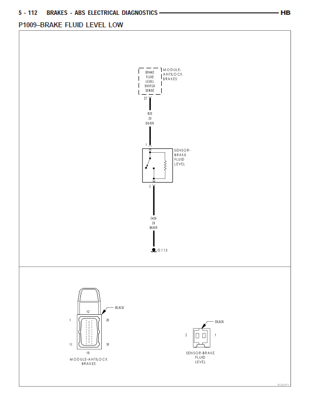
This makes sense (no pun intended) if the circuit is going to be monitored. It also explains the resistance of 9.9 kohms you are seeing across the sensor terminals, as well as the code setting criteria of seeing over 4.9 volts 5 seconds. Obviously, it has to see less than 4.9 volts and it's likely sending the 5v reference across that circuit for monitoring. There is a troubleshooting tree in the 04 manual and while it doesn't mention what the resistance spec should be, it does say that if it's over 11kohms that the sensor should be replaced. Seems to me if you have any corrosion or other problem in the sensor connector pins, at the ground (G114), or even at the FCM, or possibly at the TIPM, you could get the code you're getting. Since the code is being set by the FCM it makes me not suspect the TIPM. Can you get a resistance reading from between the FCM, at the sense line, through the sensor, and G114?
Please Log in or Create an account to join the conversation.
- W8up4Rick
-
Topic Author
- Offline
- New Member
-
- Been in the Automotive field since 2009.
- Posts: 6
- Thank you received: 5
Please Log in or Create an account to join the conversation.
- Tyler
-
- Offline
- Moderator
-
- Full time HACK since 2012
- Posts: 6124
- Thank you received: 1541
Please Log in or Create an account to join the conversation.
- billb
-
- Offline
- New Member
-
- Posts: 1
- Thank you received: 1
Seems the circuit requires a small bit of current to go through to ensure everything is connected. This worked for me and hope to save someone else some time.
Please Log in or Create an account to join the conversation.
- John Clark
-
- Offline
- Premium Member
-
- Posts: 139
- Thank you received: 46
That means that there is, indeed, a resistor in the sensor and it's not just an open/closed sensor.
Please Log in or Create an account to join the conversation.