2014 Ram 3500 6.4 Brake Sensor Codes
- fixn_junk
-
 Topic Author
- Offline
- Senior Member
-

- Posts: 55
- Thank you received: 3
Please Log in or Create an account to join the conversation.
- Tyler
-

- Offline
- Moderator
-

- Full time HACK since 2012
- Posts: 6115
- Thank you received: 1539
When the Anti-lock Brake System (ABS) Module detects that the Brake Pedal Position (BPP) Sensor is indicating less than 4.75 volts or greater than 5.25 volts for more than 500 msec.
Depending on how hard the BPP sensor is to access, I might go directly to the ABS module instead. The ABS connector is easy-ish to access once you've got the right front fender liner out of the way.
Please Log in or Create an account to join the conversation.
- fixn_junk
-
Topic Author
- Offline
- Senior Member
-
- Posts: 55
- Thank you received: 3
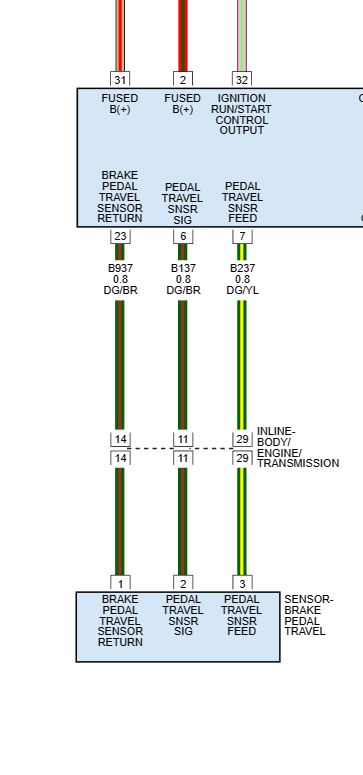
In the ag world a three wire potentiometer has power, ground and signal. The signal terminal sends the variable voltage back to the control module. In my mind terminal 3, which is sensor signal, should have the variable voltage and not terminal 2 which is sensor feed. Am I correct on this or am I misinterpreting the diagram? I also ohmed out the wires to make sure the proper terminals are connected between the sensor and the ABS module which show to be correct according to the diagram.
Please Log in or Create an account to join the conversation.
- Chad
-

- Offline
- Moderator
-
- I am not a parts changer.
- Posts: 2173
- Thank you received: 727
According to Pro Demand, at the sensor terminal 1 is sensor return, terminal 2 is sensor feed, and terminal 3 is sensor signal...am I misinterpreting the diagram?
I believe that diagram is wrong.
Here is a snippet from the OE diagram:
"Knowledge is a weapon. Arm yourself, well, before going to do battle."
"Understanding a question is half an answer."
I have learned more by being wrong, than I have by being right.
")
Please Log in or Create an account to join the conversation.
- fixn_junk
-
Topic Author
- Offline
- Senior Member
-
- Posts: 55
- Thank you received: 3
Please Log in or Create an account to join the conversation.
- Chad
-
- Offline
- Moderator
-
- I am not a parts changer.
- Posts: 2173
- Thank you received: 727
If you are certain that the signal wire is not shorted to power, external of the ABS module, during the moments that voltage jumps to 10.8 volts, then I would be confident in replacing the module.When I back probe with the sensor connected, I never have voltage on terminal 1, terminal 2 starts at 0.5v and travels up to 3.7v and then jumps to 10.8v, terminal 3 stays at 5v until I hit the point where terminal 2 jumps to 10.8v then terminal 3 jumps to 5.8v
Before I did, though, I would smack the module around, a little bit. Not only to show it who's boss, but to see if I could induce some voltage spikes on the signal wire, by doing so.
"Knowledge is a weapon. Arm yourself, well, before going to do battle."
"Understanding a question is half an answer."
I have learned more by being wrong, than I have by being right.
Please Log in or Create an account to join the conversation.
- Chad
-
- Offline
- Moderator
-
- I am not a parts changer.
- Posts: 2173
- Thank you received: 727
terminal 2 starts at 0.5v and travels up to 3.7v and then jumps to 10.8v, terminal 3 stays at 5v until I hit the point where terminal 2 jumps to 10.8v then terminal 3 jumps to 5.8v.
Is this repeatable, every time?
"Knowledge is a weapon. Arm yourself, well, before going to do battle."
"Understanding a question is half an answer."
I have learned more by being wrong, than I have by being right.
Please Log in or Create an account to join the conversation.
- fixn_junk
-
Topic Author
- Offline
- Senior Member
-
- Posts: 55
- Thank you received: 3
Also, I disconnected the ABS module and the BPP sensor checking for voltage on all three wires with the key on and had no voltage on any of the wires. It seems voltage induced as I perform the test KOEO and it repeats 100% of the time.
Please Log in or Create an account to join the conversation.
- Chad
-
- Offline
- Moderator
-
- I am not a parts changer.
- Posts: 2173
- Thank you received: 727
"Knowledge is a weapon. Arm yourself, well, before going to do battle."
"Understanding a question is half an answer."
I have learned more by being wrong, than I have by being right.
Please Log in or Create an account to join the conversation.
- fixn_junk
-
Topic Author
- Offline
- Senior Member
-
- Posts: 55
- Thank you received: 3
Please Log in or Create an account to join the conversation.
- fixn_junk
-
Topic Author
- Offline
- Senior Member
-
- Posts: 55
- Thank you received: 3
Please Log in or Create an account to join the conversation.
- fixn_junk
-
Topic Author
- Offline
- Senior Member
-
- Posts: 55
- Thank you received: 3
Disregard. It just dawned on me the module hadn't gone to sleep yet. Voltage is gone. Is it possible that if I didn't properly initialize the new switch, it could be causing all of this? My scanner doesn't give me much information on that particular process, but it appears to be completed.
Please Log in or Create an account to join the conversation.
- fixn_junk
-
Topic Author
- Offline
- Senior Member
-
- Posts: 55
- Thank you received: 3
Please Log in or Create an account to join the conversation.
- fixn_junk
-
Topic Author
- Offline
- Senior Member
-
- Posts: 55
- Thank you received: 3
Please Log in or Create an account to join the conversation.