Jeep 4.0 Secondary Ignition Waveform questions
- Graveydavey
-
 Topic Author
- Offline
- New Member
-

- Posts: 18
- Thank you received: 2
Please Log in or Create an account to join the conversation.
- juergen.scholl
-

- Offline
- Platinum Member
-

- Active partschanger
- Posts: 1230
- Thank you received: 462
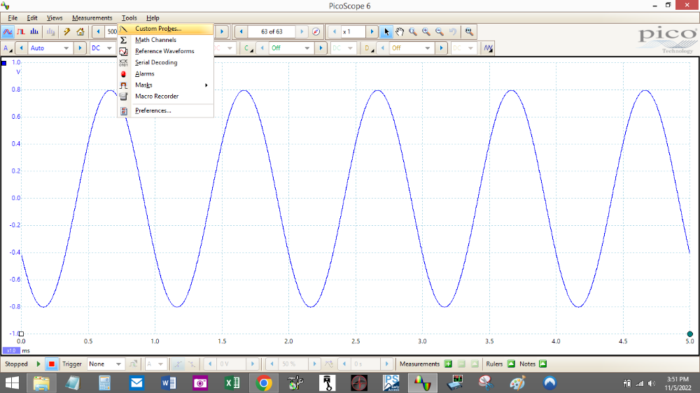
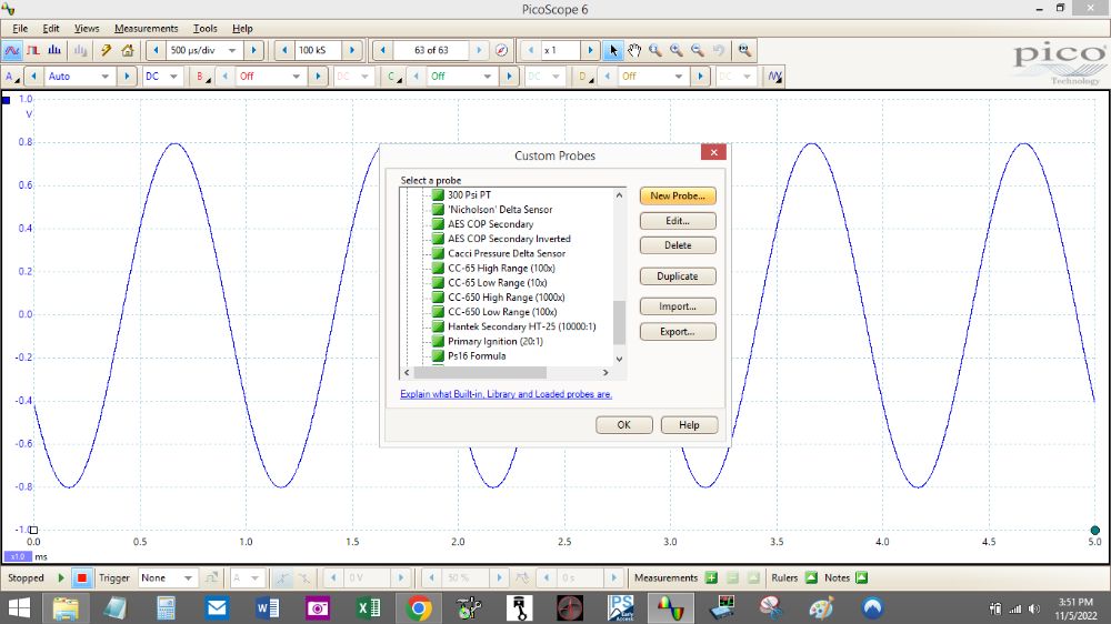
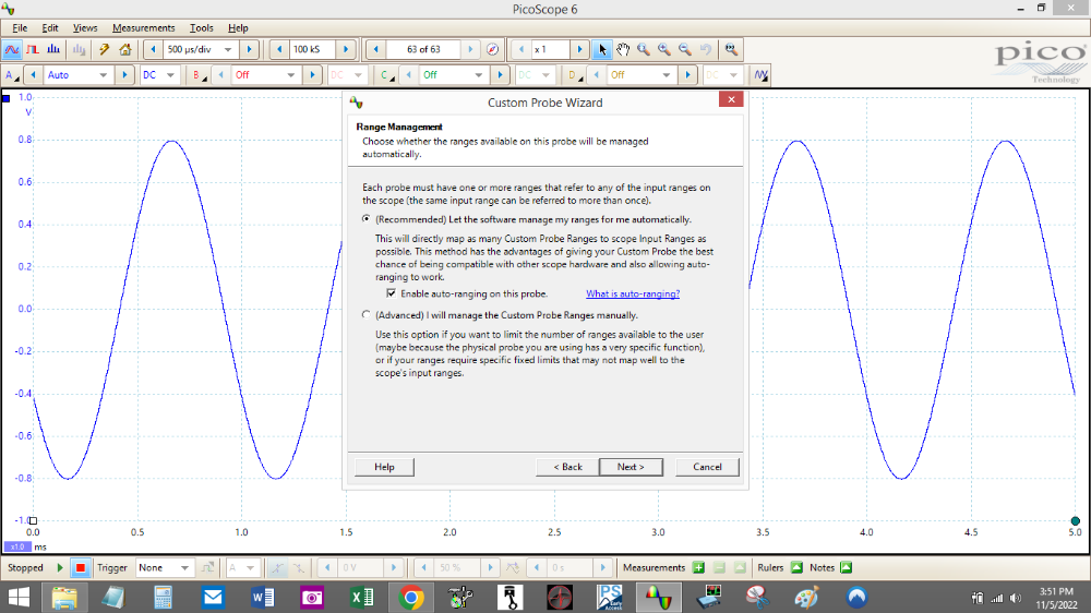
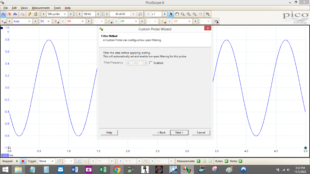
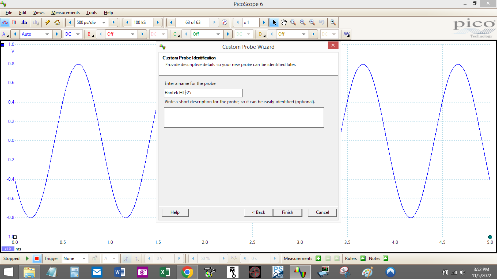
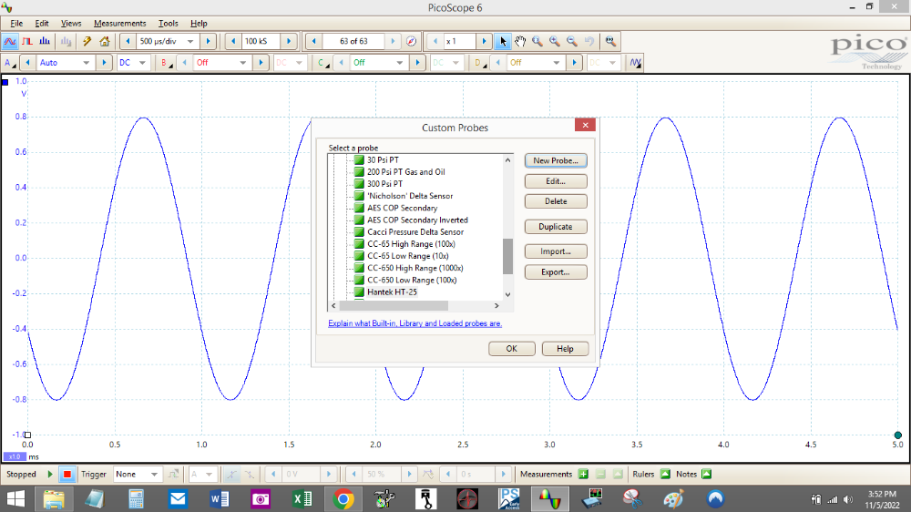
I don't see a probes menu in the software. I do have a Custom Probes list under the Tools menu, but I don't see a secondary ignition - inverted option on that list.
Maybe the probes menu is somewhere else. Any ideas? Thanks again.
The secondary ignition option is covered in the picoscope automotive software. You seem to be running the standard pico 6 software, not the automotive one.
An expert is someone who knows each time more on each time less, until he finally knows absolutely everything about absolutely nothing.
Please Log in or Create an account to join the conversation.
- Graveydavey
-
Topic Author
- Offline
- New Member
-
- Posts: 18
- Thank you received: 2
Please Log in or Create an account to join the conversation.
- Graveydavey
-
Topic Author
- Offline
- New Member
-
- Posts: 18
- Thank you received: 2
Please Log in or Create an account to join the conversation.
- juergen.scholl
-
- Offline
- Platinum Member
-
- Active partschanger
- Posts: 1230
- Thank you received: 462
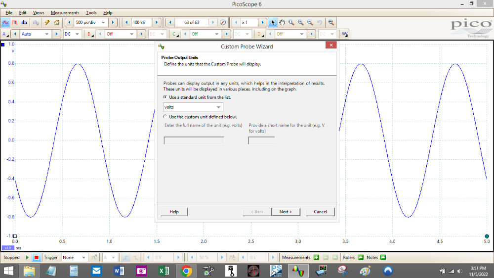
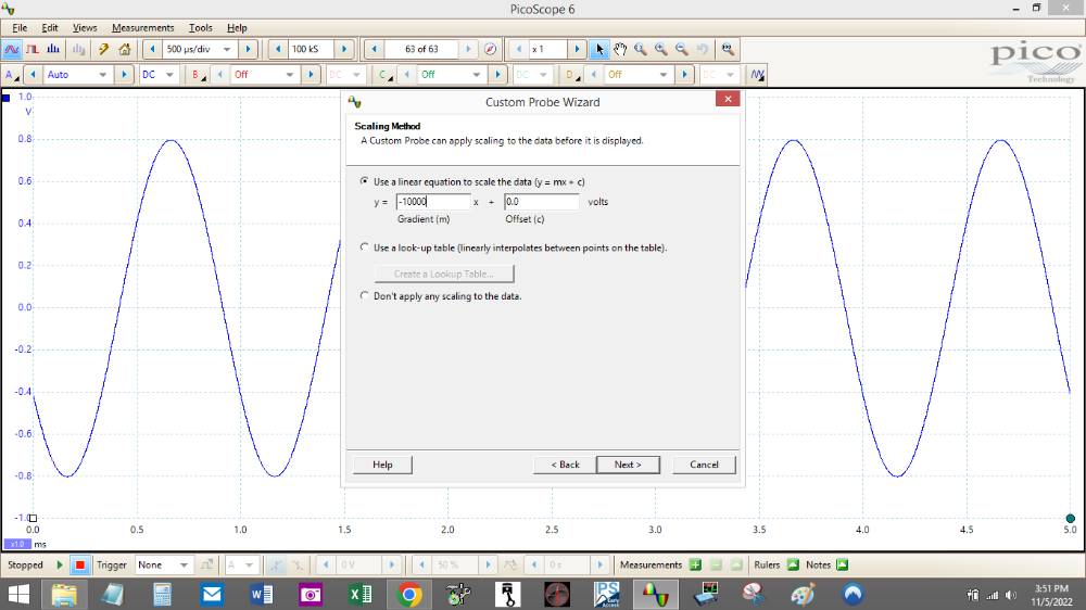
Why don't you just follow Chad's advice to apply a math channel , multiplying by -1? Do you know how to do that or does it sound unfamiliar to you?
An expert is someone who knows each time more on each time less, until he finally knows absolutely everything about absolutely nothing.
Please Log in or Create an account to join the conversation.
- Paul P.
-

- Offline
- Platinum Member
-
- Posts: 455
- Thank you received: 195
Never stop Learning.
Please Log in or Create an account to join the conversation.
- Graveydavey
-
Topic Author
- Offline
- New Member
-
- Posts: 18
- Thank you received: 2
I retested the fuel pressure today and it seems good with the mechanical gauge. PSI was 30 psi. With a throttle snap it rose to about 35 psi then dropped to about 27 and settled back in at 30. Not too jumpy really. Pulled the vacuum line on the fuel pressure regulator and it rose to about 39 psi. the check valve held pressure for 25 minutes.
I'm not sure what to make of this problem. Jeep seems to run okay aside from the hesitation/stumble around 65-70 mph. The first attachment is a throttle snap, the 2nd is an inverted shot cruising when the Jeep is stumbling. The rpm doesn't seem to be interrupted when this happens, you mostly feel it in the seat.
Please Log in or Create an account to join the conversation.
- Graveydavey
-
Topic Author
- Offline
- New Member
-
- Posts: 18
- Thank you received: 2
the plugs are clean even a little white on the electrodes.
Spark plug wires were all 4-5 k ohm in resistance.
Swapped coils again. No change in behavior. I did measure 12 ohms of resistance on the ignition control module. Kind of high, but that's not ridiculously high.
Please Log in or Create an account to join the conversation.
- Paul P.
-
- Offline
- Platinum Member
-
- Posts: 455
- Thank you received: 195
1. You got pictures of sparks.
2. Your fuel pressure looks good.
Though the fuel pressure seemed to test well with the mechanical gauge at WOT it leaned out, ran below 1 volt
In Global OBDII mode with a scan tool, you should see the B1S1 sensor reading between 0.1v(lean) and 0.9V(rich) and switching lean/rich, rich/lean once fully warmed up.
If you are pegged lean <0.3V at WOT you've got a fuel delivery issue.
Is the B1S2 also pegged lean under 0.3 volts as well?
I really wouldn't want to say much about the spark captures, because, for the most part, they could be normal at high rpm when there is lots of turbulence in the combustion chambers, but the others you have looked fairly normal, and it also looks like you upped the sample rate as well. So the first batch of pics was more than likely a sampling issue.
Also, it would be good to know what the fuel trims are doing at idle in park, then on a 65 Mph run.
Jumping straight to the scope isn't always the best scenario in driveability issues, the scan tool can answer many questions first, then possibly lead to oscilloscope testing.
Some scan tool data would be beneficial.
Never stop Learning.
Please Log in or Create an account to join the conversation.
- Graveydavey
-
Topic Author
- Offline
- New Member
-
- Posts: 18
- Thank you received: 2
A couple of weeks ago, I was chasing this down as a trans issue.
Please Log in or Create an account to join the conversation.
- Graveydavey
-
Topic Author
- Offline
- New Member
-
- Posts: 18
- Thank you received: 2
Please Log in or Create an account to join the conversation.
- Graveydavey
-
Topic Author
- Offline
- New Member
-
- Posts: 18
- Thank you received: 2
I think I should start looking elsewhere for the cause of my problem. I am going to test the rest of the sensors with the scope since I have it set up. I've test them all previously with my Fluke, but what the heck.
When the hesitation/stumble started, I thought it might be a torque converter lockup issue. I might take another look at that. I've been under the car looking around for indications of problem with the driveshafts, but I haven't seen anything out of the ordinary.
Please Log in or Create an account to join the conversation.
- Paul P.
-
- Offline
- Platinum Member
-
- Posts: 455
- Thank you received: 195
Never stop Learning.
Please Log in or Create an account to join the conversation.
- Graveydavey
-
Topic Author
- Offline
- New Member
-
- Posts: 18
- Thank you received: 2
Here's another thought. I put remanned fuel injectors in when I reinstalled the engine. How would I go about testing them to make sure they are delivering the proper amount of fuel? Pulse time, I guess?
Please Log in or Create an account to join the conversation.
- Graveydavey
-
Topic Author
- Offline
- New Member
-
- Posts: 18
- Thank you received: 2
Looking over these two waveforms again. I don't get what's going on. Why such different results?
Please Log in or Create an account to join the conversation.
- Chad
-

- Offline
- Moderator
-

- I am not a parts changer.
- Posts: 2161
- Thank you received: 725
If you capture a waveform of the crankshaft position sensor, you can use the frequency of the signal to determine if the "fish-bite" is a misfire, or Torque Converter shudder. When you feel the "stumble", If it is a misfire, the frequency will drop. If it is TC shudder, the frequency will rise. Here is an image of crankshaft frequency with a vehicle with TC shudder.I drove the car again to play around the torque converter lockup. I wired in a switch that would cut the signal to lock up the torque converter. What I noticed was that that the stumble seems to be less when the torque converter isn't locked. It's still there, but its like the torque converter is cushioning it. That thought leads me back to a problem with the motor.
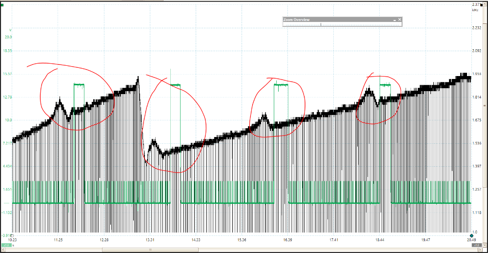
When I felt the shudder, I manually pulsed a PowerProbe and captured it on the Green channel. The Black trace is the Crankshaft frequency, as I am accelerating. The big drop in the Black trace is a Gear change.
Is it normal for the firing line voltage to drop during a throttle snap? Looking over these two waveforms again. I don't get what's going on. Why such different results?
I believe, you are still under-sampling. You should be somewhere in the range of 1-3 million samples per second.
"Knowledge is a weapon. Arm yourself, well, before going to do battle."
"Understanding a question is half an answer."
I have learned more by being wrong, than I have by being right.
")
Please Log in or Create an account to join the conversation.
- Graveydavey
-
Topic Author
- Offline
- New Member
-
- Posts: 18
- Thank you received: 2
Please Log in or Create an account to join the conversation.
- Graveydavey
-
Topic Author
- Offline
- New Member
-
- Posts: 18
- Thank you received: 2
Please Log in or Create an account to join the conversation.
- Graveydavey
-
Topic Author
- Offline
- New Member
-
- Posts: 18
- Thank you received: 2
Please Log in or Create an account to join the conversation.
- Chad
-
- Offline
- Moderator
-
- I am not a parts changer.
- Posts: 2161
- Thank you received: 725
My attempt at capturing the crankshaft position sensor while the fish bite was happening didn't reveal much. Nothing dramatic like yours. I'm still learning how to manipulate these time and voltage settings.
That is a good crank capture. And it is a good start.
")
(However, you have AC coupling selected. Even though the crank signal is an AC sine-wave, you should use DC coupling. AC coupling will hide the base voltage of the waveform. AC coupling is, primarily, used as a zoom feature. Pico's zoom capabilities are so good that AC coupling is, rarely, needed.)
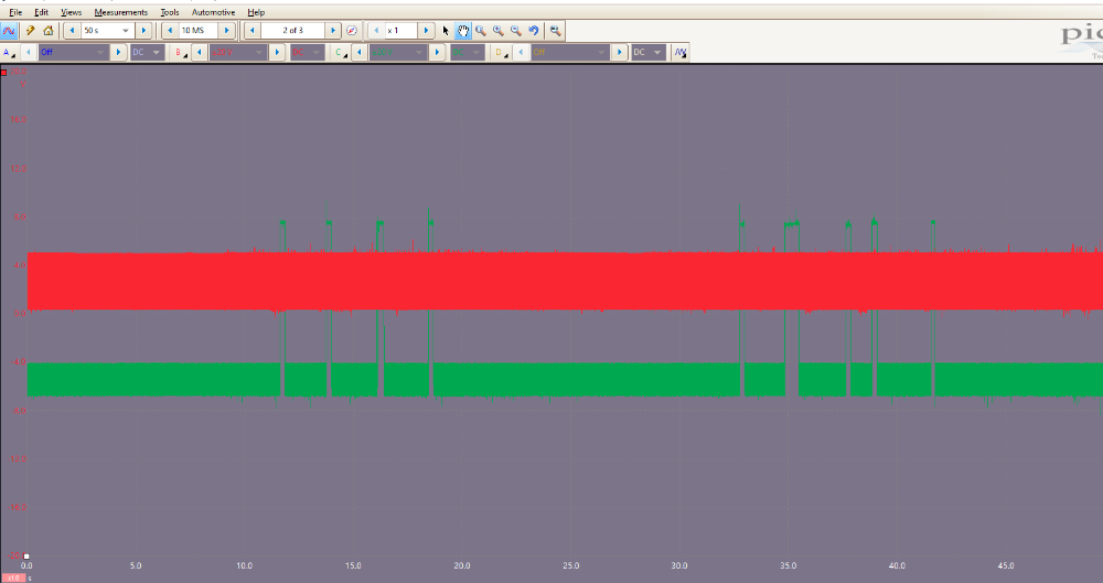
The image that I posted was not a raw capture of the crank signal. It was the FREQUENCY of the Crank signal...an average of how fast the crank signal cycled from high to low, created with a "Math Channel".
The raw capture looks like this, WITHOUT the frequency math channel:
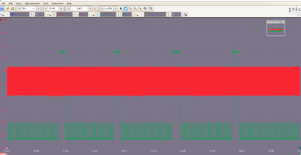
This is the same zoom level as the image of the PROCESSED FREQUENCY that I, previously, posted:
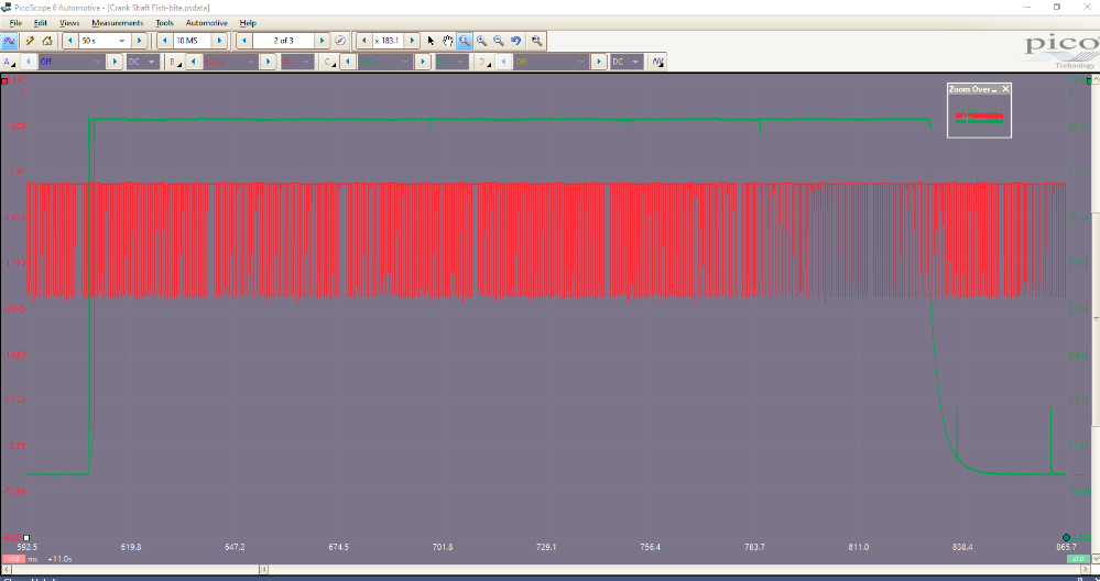
This is zoomed to inside of one of the green power probe pulses, which is close to the zoom level of your capture:
"Knowledge is a weapon. Arm yourself, well, before going to do battle."
"Understanding a question is half an answer."
I have learned more by being wrong, than I have by being right.
Please Log in or Create an account to join the conversation.