Help us help you. By posting the year, make, model and engine near the beginning of your help request, followed by the symptoms (no start, high idle, misfire etc.) Along with any prevalent Diagnostic Trouble Codes, aka DTCs, other forum members will be able to help you get to a solution more quickly and easily!
Electronic Throttle body actuator 2013 mini countryman
- radmilakrejci1
-
 Topic Author
- Offline
- New Member
-

Less
More
- Posts: 14
- Thank you received: 1
3 years 4 months ago - 3 years 4 months ago #58773
by radmilakrejci1
Electronic Throttle body actuator 2013 mini countryman was created by radmilakrejci1
Hi Paul!
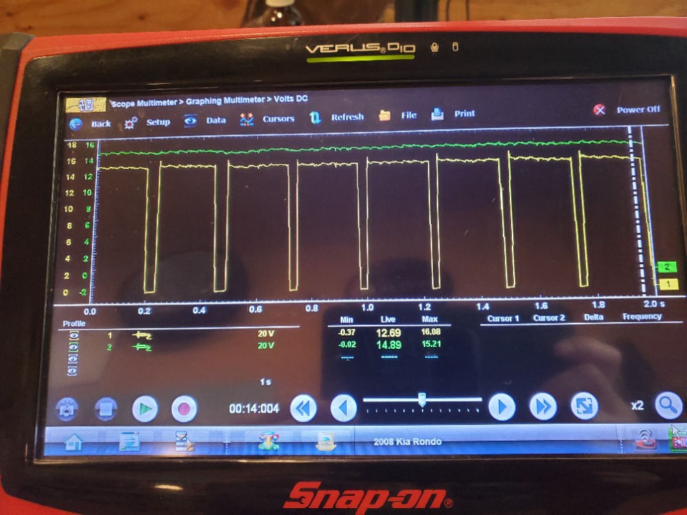
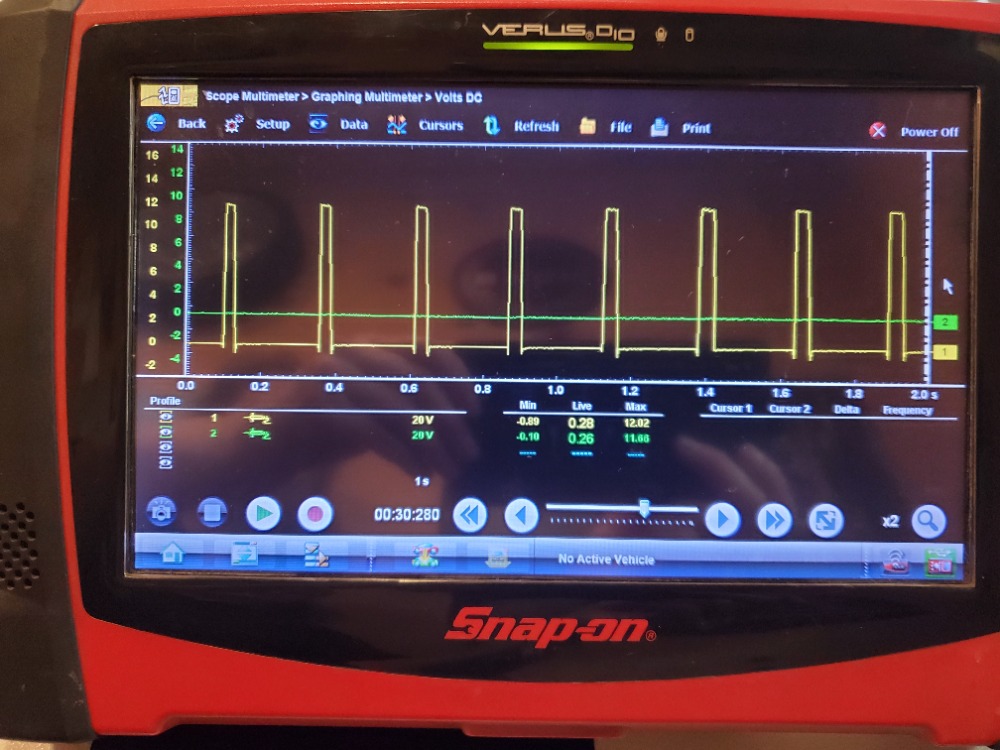 would you call this bad pcm driver on green trace. this is waveform of 2 wires from DC motor on Electric Throttle body actuator (2013 cooper countryman). It uses H bridge in PCM to control/switch polarities. I would assume that green trace should switch 0-12V like the yellow one just in mirror image. First pic is with engine idling, second with cycling key. I noticed driver not being "opened-stuck " by seeing battery voltage with engine idling and seeing 0V with key cycling on green trace, but definitely transistor switching on/off not taking place. This computer is $2000 so I wanna be 100% sure before I tell customer that's what is needed. thank you
Problem with this car is IT WON'T ACCERELATE !!! IT IDLES FINE BUT WON'T GO ABOVE 15MPH
This is the description from BMW/Mini:
The engine control calculates the position of the throttle valve: from the position of the accelerator pedal and the torque request by other control units. The position of the throttle valve is monitored without contact in the electromotive throttle actuator by 2 hall effect sensors. The electromotive throttle actuator is opened or closed electrically by the engine control. The charging pressure also influences the position of the throttle valve.
A position sensor is integrated into the electromotive throttle actuator. A voltage of 5 volts is supplied to the position sensor by the engine control, which also provides the ground. 2 data lines ensure a redundant throttle valve position feedback signal to the engine control.
The servomotor that activates the throttle flap is a direct current motor. This is done using an H bridge which means the motor can also be activated in the opposing direction. The H bridge in the engine control is monitored by the diagnostic system.
Last edit: 3 years 4 months ago by radmilakrejci1. Reason: DRIVIBILITY ISSUES
Please Log in or Create an account to join the conversation.
- Noah
-

- Offline
- Moderator
-

- Give code definitions with numbers!
Less
More
- Posts: 5005
- Thank you received: 1116
3 years 4 months ago #58774
by Noah
"Ground cannot be checked with a 10mm socket"
Replied by Noah on topic Electronic Throttle body actuator 2013 mini countryman
It looks to me as though the green trace is representing a constant ground or constant power, and the yellow trace is leg of the circuit doing the "driving" of the motor depending on if the throttle should be opening or closing.
I have blessed little experience with Mini, but based only on those two captures, I don't immediately get the feeling that the PCM is bad
I have blessed little experience with Mini, but based only on those two captures, I don't immediately get the feeling that the PCM is bad
"Ground cannot be checked with a 10mm socket"
Please Log in or Create an account to join the conversation.
- radmilakrejci1
-
Topic Author
- Offline
- New Member
-
Less
More
- Posts: 14
- Thank you received: 1
3 years 4 months ago #58776
by radmilakrejci1
Replied by radmilakrejci1 on topic Electronic Throttle body actuator 2013 mini countryman
I don't think green trace should be constant ground or power. Remember that motor needs current flow which needs ground and power at the same time. So when one wire for motor is high, other wire has to be low and since one wire is pulsing 12-0 square wave, in order for current flow to happen, the other wire has to be pulsing 12-0 in mirror image. This is exactly same concept as Paul describes in 4 wire stepper motor for IAC valve with H bridge inside of PCM. Only difference is I have one coil (motor) not 2 like 4 wire stepper motor.
Please Log in or Create an account to join the conversation.
- Noah
-
- Offline
- Moderator
-
- Give code definitions with numbers!
Less
More
- Posts: 5005
- Thank you received: 1116
3 years 4 months ago #58777
by Noah
"Ground cannot be checked with a 10mm socket"
Replied by Noah on topic Electronic Throttle body actuator 2013 mini countryman
When the green channel is high, the yellow drives low, when it's low, the yellow drives high. In my opinion, that should be enough to move the throttle in both directions.
"Ground cannot be checked with a 10mm socket"
Please Log in or Create an account to join the conversation.
- Noah
-
- Offline
- Moderator
-
- Give code definitions with numbers!
Less
More
- Posts: 5005
- Thank you received: 1116
3 years 4 months ago #58778
by Noah
"Ground cannot be checked with a 10mm socket"
Replied by Noah on topic Electronic Throttle body actuator 2013 mini countryman
But, like I said, Mini is not my forte...
"Ground cannot be checked with a 10mm socket"
Please Log in or Create an account to join the conversation.
- radmilakrejci1
-
Topic Author
- Offline
- New Member
-
Less
More
- Posts: 14
- Thank you received: 1
3 years 4 months ago #58780
by radmilakrejci1
Replied by radmilakrejci1 on topic Electronic Throttle body actuator 2013 mini countryman
Noah! You need to watch this video and study the waveforms Paul had privided there to understand that both wires should be identical and mirroring one another. In that video, flat line on 2nd wire of the coil means open pcm driver.
IAC STEPPER TESTING PART 2
IAC STEPPER TESTING PART 2
The following user(s) said Thank You: Noah
Please Log in or Create an account to join the conversation.
- Noah
-
- Offline
- Moderator
-
- Give code definitions with numbers!
Less
More
- Posts: 5005
- Thank you received: 1116
3 years 4 months ago - 3 years 4 months ago #58784
by Noah
"Ground cannot be checked with a 10mm socket"
Replied by Noah on topic Electronic Throttle body actuator 2013 mini countryman
www.scannerdanner.com/scannerdanner-prem...-testing-part-2.html
That's a good lesson, I like the classroom lectures. You'll notice that the failed driver only flat lined while disconnected, when connected that control wire mimicked the functioning driver.
The first car in my bay today was a GM with an electric throttle so I busted out the scope. Both motor control wires hang at 12v until movement is needed, then one leg is pulsed to ground or the other, depending naturally on which direction and how quickly it needs to move.
At no time did the pattern look like the stepper motor example in the video with both circuits being driven opposite of each other.
I'm here to learn like everyone else, so please let us know how you make out. In the mean time I'll keep scoping TAC motor control circuits
"Ground cannot be checked with a 10mm socket"
Last edit: 3 years 4 months ago by Noah.
Please Log in or Create an account to join the conversation.
- radmilakrejci1
-
Topic Author
- Offline
- New Member
-
Less
More
- Posts: 14
- Thank you received: 1
3 years 4 months ago #58785
by radmilakrejci1
Replied by radmilakrejci1 on topic Electronic Throttle body actuator 2013 mini countryman
Noah. You are absolutely right! I remembered in Pauls video that it only flat lined when disconnected and when connected, it was backfeeding from working driver.. Also I knew that my driver is not open because when its taken with cycled key voltage is fixed high, when its taken during idle it is fixed low so that is a confirmation that driver switch closes/opens. Thats whats confusing for me.
I do appreciate A LOT you taking your time and testing ETC on GM you have in the shop but remember we can't compare apples and pears. I think that not all ETC motors are same and that you need to know motor design. This will make a difference in what the waveform will look like. this car uses H bridge which is very important (exactly like Paul has hand drawn for his IAC stepper motor. So I still believe that my waveform on this mini should be identical to Pauls hand drawn. I will definitely keep you posted. You are certainly aware that BMW and Audi are know for overcomplicating things.
Also it would really be helful for all of us if you did capture that waveform on that GM and share, as Paul doesn't have any good waveforms listed in his book on ETC topic
thank so much
Please Log in or Create an account to join the conversation.
- Noah
-
- Offline
- Moderator
-
- Give code definitions with numbers!
Less
More
- Posts: 5005
- Thank you received: 1116
3 years 4 months ago #58851
by Noah
"Ground cannot be checked with a 10mm socket"
Replied by Noah on topic Electronic Throttle body actuator 2013 mini countryman
Yes sir, I will post the waveform here. Just been busy.
In the meanntime, I encourage you to take advantage of the guided component tests for the TAC in your Snap On tool.
If you chose guided component tests without selecting a vehicle, the very last tab in manufacturers is for training. There are various 10-20min classes on different automotive technologies, including a 20min tutorial on various electric throttle body designs.
"Ground cannot be checked with a 10mm socket"
Please Log in or Create an account to join the conversation.
- Noah
-
- Offline
- Moderator
-
- Give code definitions with numbers!
Less
More
- Posts: 5005
- Thank you received: 1116
3 years 4 months ago #58854
by Noah
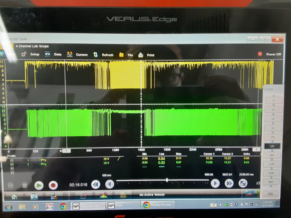
My Verus doesn't want to display my scope captures right now...
But here's a photo of the waveforms fromTAC control circuits KOEO while moving the pedal from an 04 Explorer.
"Ground cannot be checked with a 10mm socket"
Replied by Noah on topic Electronic Throttle body actuator 2013 mini countryman
My Verus doesn't want to display my scope captures right now...
But here's a photo of the waveforms fromTAC control circuits KOEO while moving the pedal from an 04 Explorer.
"Ground cannot be checked with a 10mm socket"
Please Log in or Create an account to join the conversation.
Time to create page: 0.331 seconds