Homemade Pressure Transducers--Unexpected Results
- Joshasta
-
 Topic Author
- Offline
- Junior Member
-

- Posts: 28
- Thank you received: 3
Please Log in or Create an account to join the conversation.
- juergen.scholl
-

- Offline
- Platinum Member
-

- Active partschanger
- Posts: 1233
- Thank you received: 462
Concerning the amplitude of the ac wave and the missing signal: you may have created some weird back feed/ground loop issue with this USB charger.... Where is your signal ground placed at and did the Versus run on battery or ac power supply?
An expert is someone who knows each time more on each time less, until he finally knows absolutely everything about absolutely nothing.
Please Log in or Create an account to join the conversation.
- Matt T
-
- Offline
- Platinum Member
-
- Posts: 751
- Thank you received: 276
Also FWIW I scoped a few wall warts before I found a good one with clean output.
Please Log in or Create an account to join the conversation.
- Noah
-

- Offline
- Moderator
-

- Posts: 5046
- Thank you received: 1122
Please Log in or Create an account to join the conversation.
- Joshasta
-
Topic Author
- Offline
- Junior Member
-
- Posts: 28
- Thank you received: 3
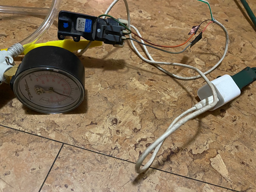
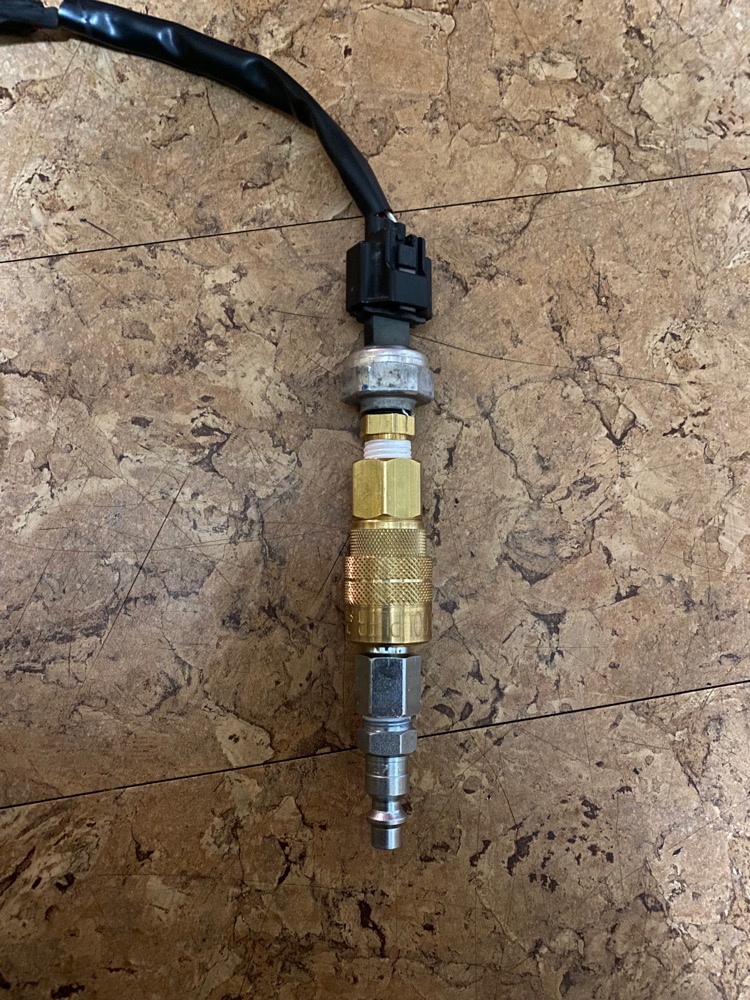
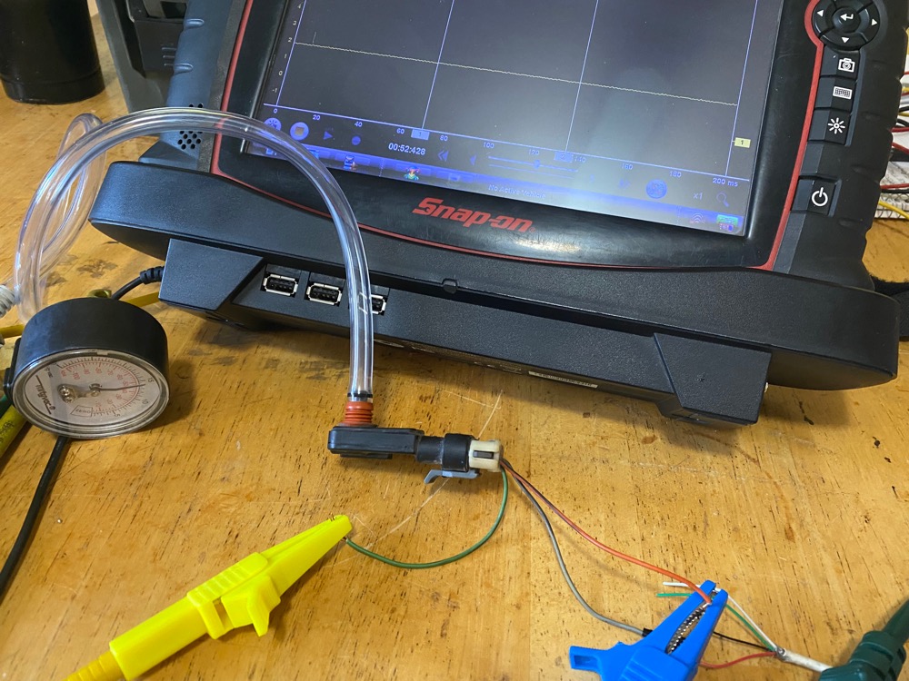
I will be testing the AC Pressure Switch with air pressure today and hopefully doing some in-cylinder pressure tests. I will be using the same switch out a Nissan Altima as you have mentioned Noah.
Please Log in or Create an account to join the conversation.
- Joshasta
-
Topic Author
- Offline
- Junior Member
-
- Posts: 28
- Thank you received: 3
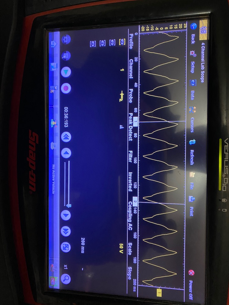
I got nice linear rise in voltage from 50-100psi testing it with my leak down tester. But I didn't get a good waveform in-cylinder. I tried different settings. This is the best I got. Any other suggestions for probe selection or anything?
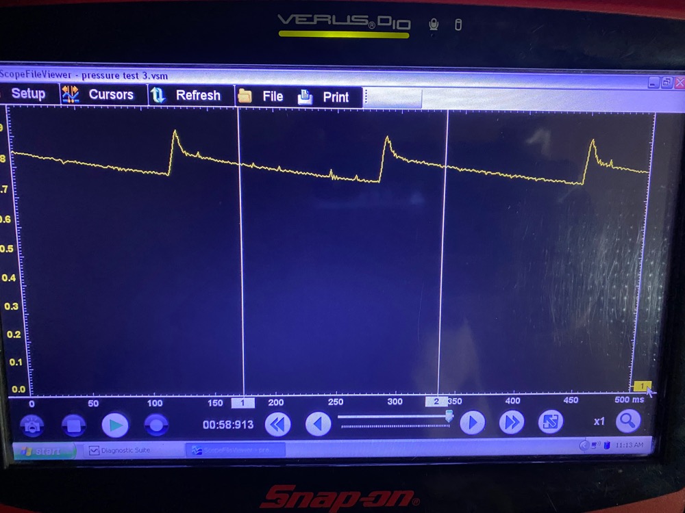
Please Log in or Create an account to join the conversation.
- Matt T
-
- Offline
- Platinum Member
-
- Posts: 751
- Thank you received: 276
Please Log in or Create an account to join the conversation.
- Joshasta
-
Topic Author
- Offline
- Junior Member
-
- Posts: 28
- Thank you received: 3
Please Log in or Create an account to join the conversation.
- Noah
-
- Offline
- Moderator
-
- Posts: 5046
- Thank you received: 1122
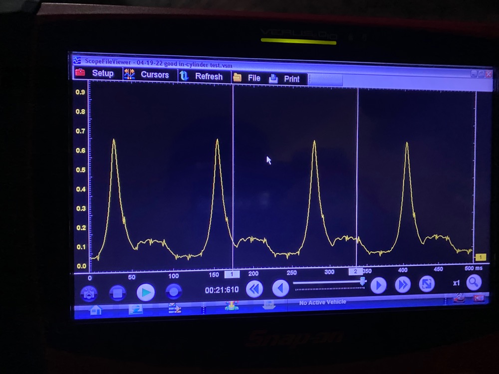
That's an interesting waveform, is there any running issue in that engine?
Please Log in or Create an account to join the conversation.
- Paul P.
-

- Offline
- Platinum Member
-
- Posts: 457
- Thank you received: 195
Granted I couldn't perfectly match the cylinder chart of due to the angle of the picture!
Never stop Learning.
Please Log in or Create an account to join the conversation.
- Joshasta
-
Topic Author
- Offline
- Junior Member
-
- Posts: 28
- Thank you received: 3
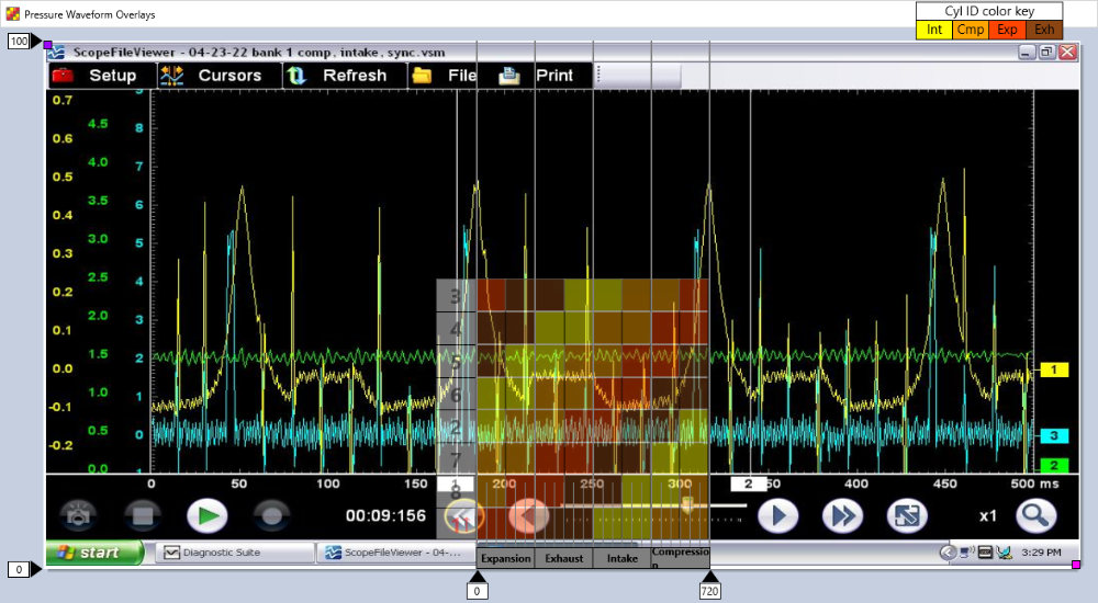
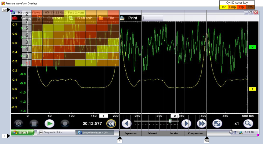
I have been studying in-cylinder waveforms, I have the Microsoft overlay program, and I have noticed that area circled, exhaust valve closing to slowly it looks like? And also I have been looking at the pockets. The expansion pocket doesn't appear to be as deep as the intake. That may be pointing towards timing problem I am reading?
The engine doesn't have any major running problems. Fuel trims and power is good. no engine codes. It has an exhaust leak on a different cylinder... Engine does have 200K. I am going to check a different cylinder soon
Please Log in or Create an account to join the conversation.
- Joshasta
-
Topic Author
- Offline
- Junior Member
-
- Posts: 28
- Thank you received: 3
Please Log in or Create an account to join the conversation.
- juergen.scholl
-
- Offline
- Platinum Member
-
- Active partschanger
- Posts: 1233
- Thank you received: 462
It is called Engine Mechanical Testing 2, covers in-cylinder text Ng as well as intake, exhaust and crankcase pressure testing. He uses case studies to explain theory and practice of the diagnostic proces.
I do not hesitate a second to recommend this class to any one interested in this topic.
automotiveseminars.com/online-training-events/
An expert is someone who knows each time more on each time less, until he finally knows absolutely everything about absolutely nothing.
Please Log in or Create an account to join the conversation.
- juergen.scholl
-
- Offline
- Platinum Member
-
- Active partschanger
- Posts: 1233
- Thank you received: 462
Was this capture made with an 8 bit vertical resolution or is it just the response time of your sensor?
Anyhow, you may want to crank up the sampling rate significantly.
An expert is someone who knows each time more on each time less, until he finally knows absolutely everything about absolutely nothing.
Please Log in or Create an account to join the conversation.
- Paul P.
-
- Offline
- Platinum Member
-
- Posts: 457
- Thank you received: 195
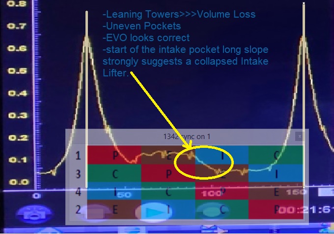
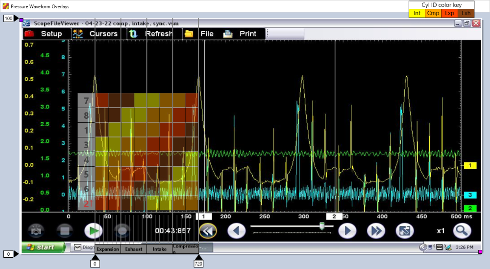
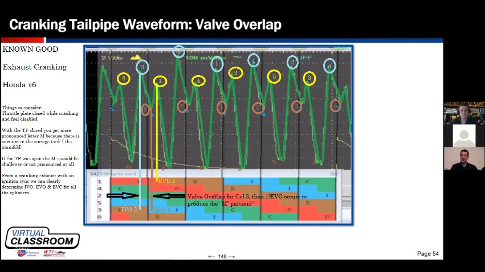
and I have noticed that area circled, exhaust valve closing too slowly it looks like?
Exhaust Valve Close is not a good marker to use, because it happens during the overlap with the Intake valve. This is an Intake valve opening up slowly. This really shouts out a lifter issue, as opposed to a spring issue.
The Exhaust Valve Open and the Intake Valve Close are usually good markers to use to determine timing issues. Yours look reasonable.
Your Towers are leaning, and your pockets are uneven. This signifies a volume loss. This cylinder will have lower compression than the other.
Perform a Relative Compression test with an Ignition sync, I think this cylinder would be lower on compression.
What would put the nail in the coffin would be to have an FLS ( Piezo Pulse Sensor ) in the Intake with an ignition sync on this one!
Here is some great info on In-cylinder Diagnostics with none other than Brandon Steckler himself:
And the legendary mad scientist Bernie Thompson:
Never stop Learning.
Please Log in or Create an account to join the conversation.
- Joshasta
-
Topic Author
- Offline
- Junior Member
-
- Posts: 28
- Thank you received: 3
Please Log in or Create an account to join the conversation.
- Paul P.
-
- Offline
- Platinum Member
-
- Posts: 457
- Thank you received: 195
Kudos to you for doing for building and experimenting. Airflow diagnostics is an Awesome tool for non-intrusive engine mechanical testing.
Many of us have been down this road, and it was a great learning experience.
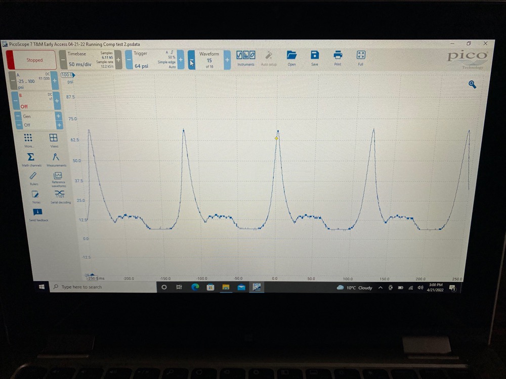
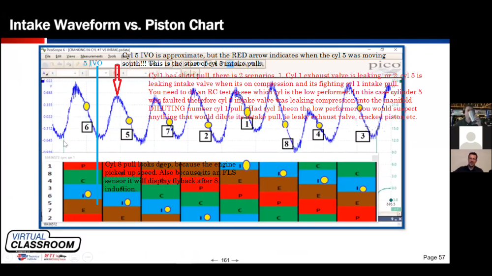
I noticed this flat spot on the waveform:
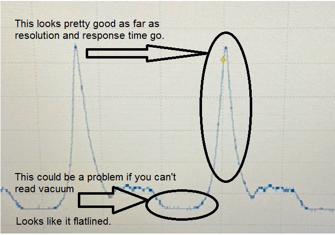
Here is a good fix for a homemade sensor, all it does is allow some of the signal voltage to be 'interpreted' as a vacuum. In other words, if your sensor outputs 0.5-4.5v, it would set the 'at rest/zero pressure' at ~1.5v. (You would need to measure the voltage you get if you intended to scale it)
Denis solves this flatline issue, and he's got some other interesting little builds in his gallery.
Always keep in the back of your head with pressure transducers and in-cylinder analysis;
1. Pressure Increases>>>Volume Decreases
Pressure Decreases>>>Volume Increases
2. Rate of Pressure Change.
-A good example is a leaning tower, assuming the piston speed was very constant, in your photo, pressure built faster on the compression stroke, and on the power stroke pressure is decreased slower.
Why is this? Volume is key. The cylinder inhaled less air than it normally would have so the pressure increased rapidly. Because of this smaller volume, the pressure decreases slower on the power stroke and an exhaust pocket does not get formed because the Exhaust valve opened when it should.
-when the intake valve opens we should see a sharp, almost straight down drop in pressure going in to the Intake Pocket. In your photo the rate of change is slow to decrease the pressure. This strongly suggests less volume can be inhaled by that cylinder. Remember the pressure is decreasing slower, therefore the volume must be increasing slower as well!
An FLS sensor, another super easy build, would show this cyclinder having a weak intake pull when that valve opens.
Most of all, have fun, take lots of known good captures, then the bad one's will stick out like a sore thumb!!
Never stop Learning.
Please Log in or Create an account to join the conversation.
- Joshasta
-
Topic Author
- Offline
- Junior Member
-
- Posts: 28
- Thank you received: 3
Thanks for that advise, will give it a look over forsure!
Please Log in or Create an account to join the conversation.
- Joshasta
-
Topic Author
- Offline
- Junior Member
-
- Posts: 28
- Thank you received: 3
Please Log in or Create an account to join the conversation.
- Paul P.
-
- Offline
- Platinum Member
-
- Posts: 457
- Thank you received: 195
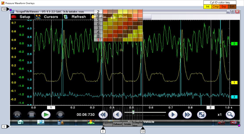
Also, it's good to isolate the crankcase from the intake manifold, so block off all PCV components.
Keep the throttle plate closed when testing to get defined intake valve movements.
That's cool to see the in-cylinder and the EVO event line up together!!
Hopefully you can read these pics,
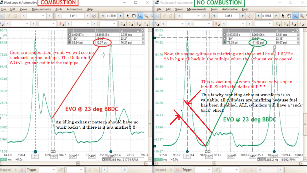
It's good to note that running exhaust FLS waveform can also identify a "miss", because no combustion means a vacuum across the face of the cylinder, just as a cranking waveform wold be!
Nice work.
Never stop Learning.
Please Log in or Create an account to join the conversation.