Blown head gasket...Which cylinder?
- Chad
-
 Topic Author
- Offline
- Moderator
-

- I am not a parts changer.
- Posts: 2199
- Thank you received: 741
2002 Chrysler PT Cruiser 2.4L Blown Head Gasket
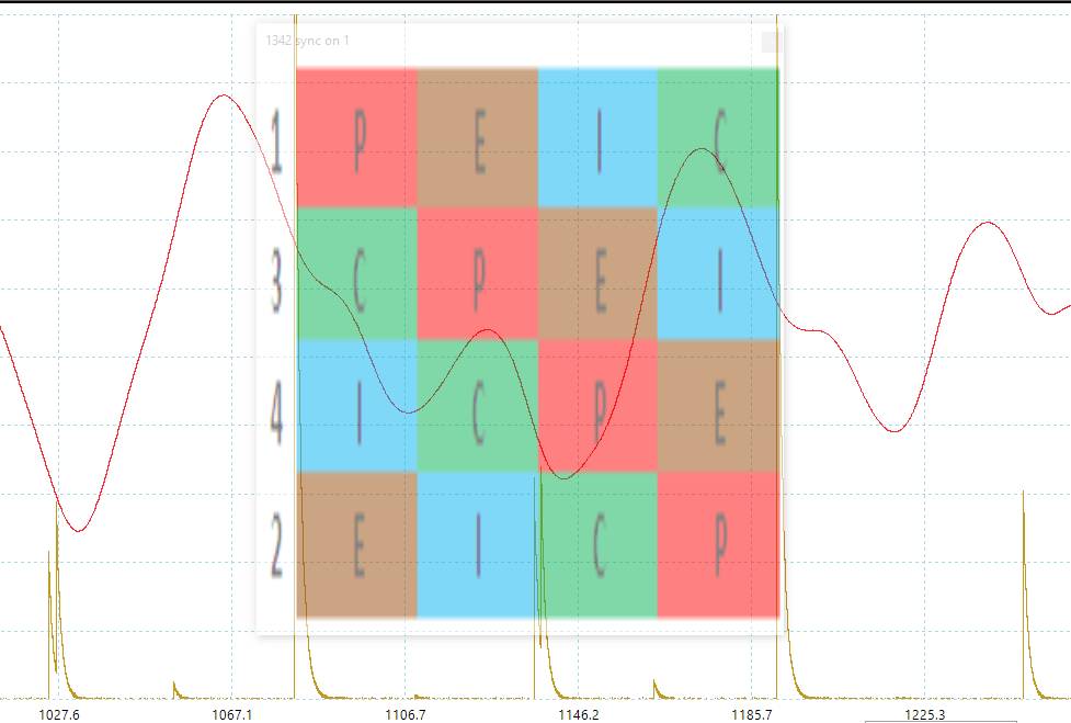
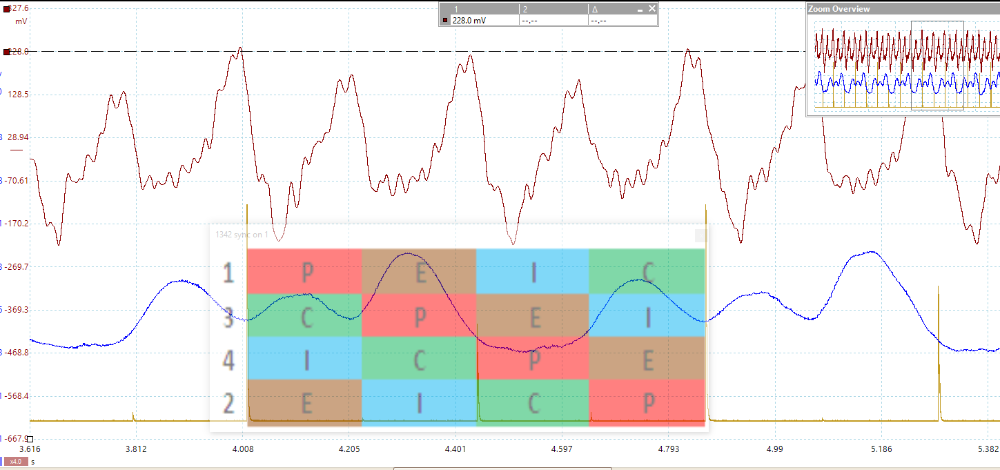
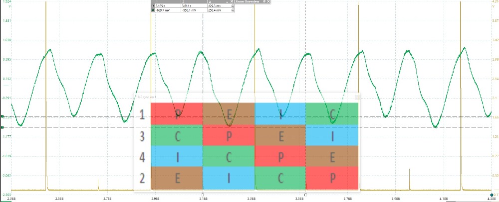
Firing Order 1-3-4-2 Sync on #1
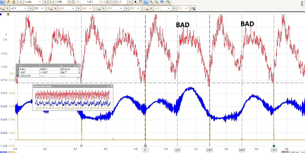
Use these waveforms to take a guess at which Cylinder is at fault.
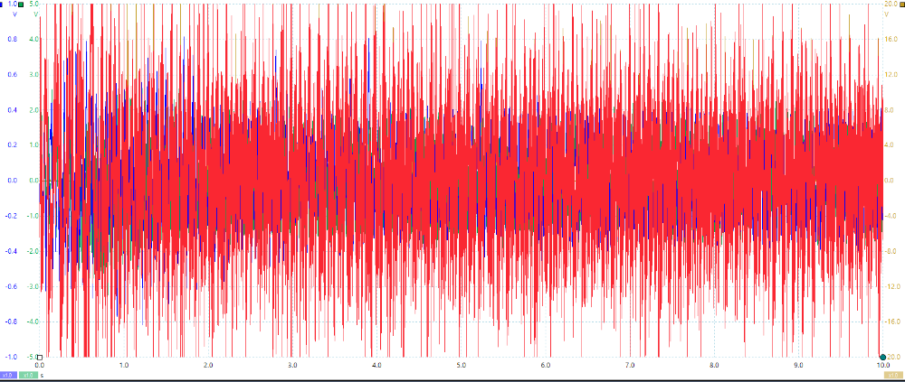
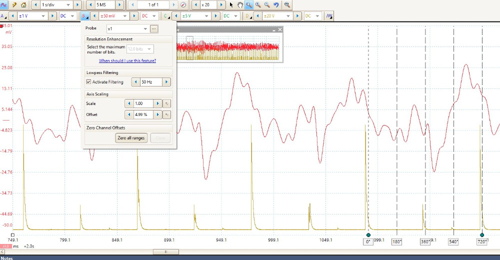
Building on Tyler's game, this time, you will need to use Filters, Zooming, and a Math Channel (RC is Voltage with AC coupling, it will need to be inverted) to "tune" the waveforms in. Here is a Screen shot of an "un-tuned" capture.
You should be able to produce, and post screenshots, of useful waveforms to determine which cylinder(s) is/are at fault.
Relative compression
drive.google.com/open?id=1JXaRRUnMAfl-KOEUIis9J_Ni4TEuvhGj
Radiator Pulses at idle
drive.google.com/open?id=1wtXiEa654PkESrYkSVmVU4HIIzOgb4C4
Radiator pulses and RC
drive.google.com/open?id=1maJ6GKa7e-YgysO33DIW4mlKxE_hTVlF
PicoScope Software
www.picoauto.com/download/software/sr/Pi...tomotive_6.14.25.exe
"Knowledge is a weapon. Arm yourself, well, before going to do battle."
"Understanding a question is half an answer."
I have learned more by being wrong, than I have by being right.
Please Log in or Create an account to join the conversation.
- Matt T
-

- Offline
- Platinum Member
-

- Posts: 751
- Thank you received: 276
Please Log in or Create an account to join the conversation.
- Matt T
-
- Offline
- Platinum Member
-
- Posts: 751
- Thank you received: 276
Please Log in or Create an account to join the conversation.
- Chad
-
Topic Author
- Offline
- Moderator
-
- I am not a parts changer.
- Posts: 2199
- Thank you received: 741
Matt T wrote: Applying a heavy low pass filter to the radiator pulses at idle makes it look like cyl #2.
Nice!
Matt T wrote: And #2 and #3 both appear to be causing pressure rises in the rad.
"Knowledge is a weapon. Arm yourself, well, before going to do battle."
"Understanding a question is half an answer."
I have learned more by being wrong, than I have by being right.
Please Log in or Create an account to join the conversation.
- Chad
-
Topic Author
- Offline
- Moderator
-
- I am not a parts changer.
- Posts: 2199
- Thank you received: 741
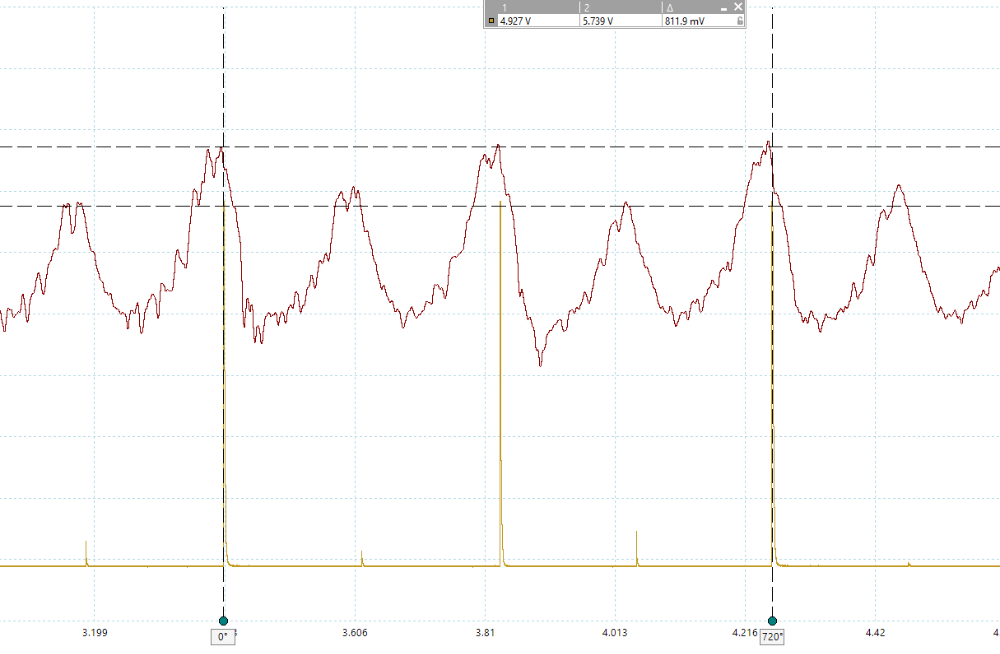
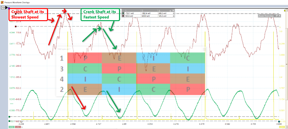
Matt T wrote: On the cranking waveform #2 definitely looks bad. Compression peak isn't terrible on #3 but the bounce back looks as bad as #2. And #2 and #3 both appear to be causing pressure rises in the rad.
You are, exactly, right. And, I am sure you know, Matt T. But for others, keep in mind that this is a voltage waveform. It is upside-down for RC. On this 4 cylinder engine and Firing Order, It looks similar to the invert. However on a 6, or 8 cylinder engine, it can look quite different.
To flip it, Go to Tools/Math Channels and check Invert B.
"Knowledge is a weapon. Arm yourself, well, before going to do battle."
"Understanding a question is half an answer."
I have learned more by being wrong, than I have by being right.
Please Log in or Create an account to join the conversation.
- Tyler
-

- Offline
- Moderator
-
- Full time HACK since 2012
- Posts: 6129
- Thank you received: 1545
Please Log in or Create an account to join the conversation.
- Paul P.
-

- Offline
- Platinum Member
-
- Posts: 457
- Thank you received: 195
Textbook Captures Mr.Coleman!
___deleted photo_____
Never stop Learning.
Please Log in or Create an account to join the conversation.
- Matt T
-
- Offline
- Platinum Member
-
- Posts: 751
- Thank you received: 276
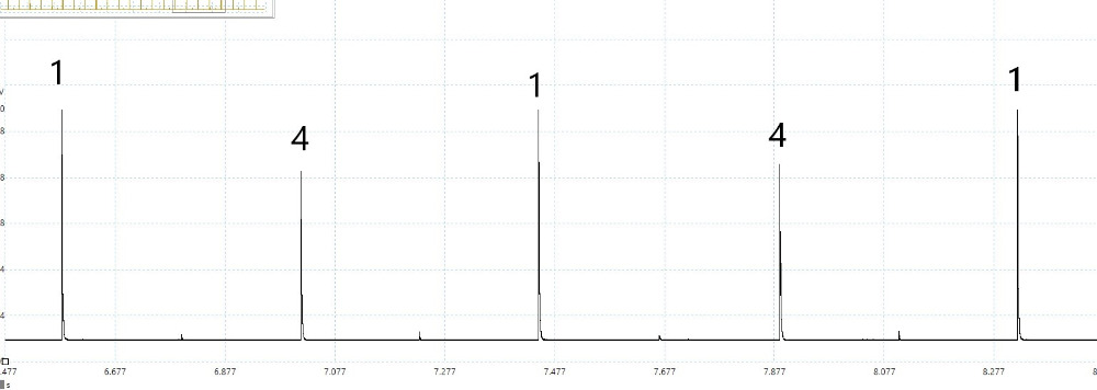
The ignition signal is waste spark taken with an inductive (RPM) pick-up. The firing events are taller than the waste sparks with this type of probe. It's a little difficult to see with this capture because the voltage scale has cropped the top off the firing events.
Please Log in or Create an account to join the conversation.
- Chad
-
Topic Author
- Offline
- Moderator
-
- I am not a parts changer.
- Posts: 2199
- Thank you received: 741
No one has posted a screen shot of the Intake Manifold waveform, yet. There is something to be seen and explained there, as well.Tyler wrote: Awwww I missed out on all the fun.
:lol:
Matt T wrote: The ignition signal is waste spark taken with an inductive (RPM) pick-up. The firing events are taller than the waste sparks with this type of probe. It's a little difficult to see with this capture because the voltage scale has cropped the top off the firing events.
Spot on, again, Matt.
"Knowledge is a weapon. Arm yourself, well, before going to do battle."
"Understanding a question is half an answer."
I have learned more by being wrong, than I have by being right.
Please Log in or Create an account to join the conversation.
- Paul P.
-
- Offline
- Platinum Member
-
- Posts: 457
- Thank you received: 195
Edit, Yes Weycraze your picture is referenced incorrectly!!!!
Thanks Chad, nice set-up!!!!
Everyone, please disregard my picture!!!!!
I need to delete it so not to misguide someone
Paul
Oh, Matt T. thank-you very much for pointing that CRUCIAL tid bit of info out to me!
Never stop Learning.
Please Log in or Create an account to join the conversation.
- Chad
-
Topic Author
- Offline
- Moderator
-
- I am not a parts changer.
- Posts: 2199
- Thank you received: 741
:oops: My apologies, Paul. It wasn't intentional. :blush: I'm going to blame it on the eScope. :dry: I have gotten use to skipping the channel/scaling setup.Weycraze wrote: Thanks Chad, nice set-up!!!!
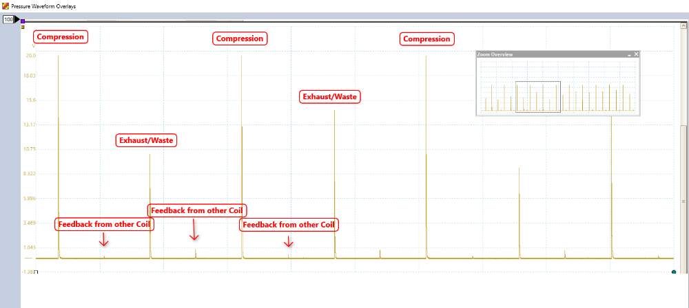
For those that missed it, my bad voltage scaling, in the first waveform, can make 360° of Crank Rotation appear to be 720° of crank rotation.
Bad Voltage Scaling:
Cylinder #1 Compression Spark and Exhaust/Waste Spark both spike over the 5 volt scale. The feedback from the other coil appears to be the waste spark event.
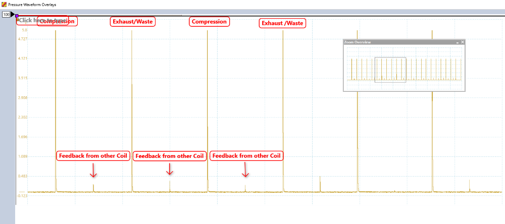
Better Voltage Scaling. With a 20 volt scale (could have been even higher), we can see Cylinder #1 spike higher on it's compression stroke than it does on the the Exhaust Stroke/Waste Spark
"Knowledge is a weapon. Arm yourself, well, before going to do battle."
"Understanding a question is half an answer."
I have learned more by being wrong, than I have by being right.
Please Log in or Create an account to join the conversation.
- Paul P.
-
- Offline
- Platinum Member
-
- Posts: 457
- Thank you received: 195
But, that is really a good thing for learning purposes. That hits home the importance of using meaningful channel syncs to help aid
in identifying cylinder events.
Also, bad on my part for 'looking' a little too quick, and assuming I was correct on the sync. Especially when looking at someone else's work!
Very good learning experience!
Never stop Learning.
Please Log in or Create an account to join the conversation.
- Donut
-
- Offline
- Senior Member
-

- Posts: 50
- Thank you received: 11
Chad wrote: No one has posted a screen shot of the Intake Manifold waveform, yet. There is something to be seen and explained there, as well.
From the looks of it cylinders #2 and #3 have a deeper intake pull than the other two due to a loss of cylinder charge through the blown head gasket. Use that with the RC and radiator pulse waveforms and you've got a pretty solid case there. Definitely a useful tool in proving out a bad gasket, and somehow a step I always seem to forget about when the time comes to use it. :whistle:
"Don't ever say 'easy' until the check clears."
Please Log in or Create an account to join the conversation.
- Chad
-
Topic Author
- Offline
- Moderator
-
- I am not a parts changer.
- Posts: 2199
- Thank you received: 741
Donut wrote: From the looks of it cylinders #2 and #3 have a deeper intake pull than the other two due to a loss of cylinder charge through the blown head gasket.
Close. You're on the right track.
"Knowledge is a weapon. Arm yourself, well, before going to do battle."
"Understanding a question is half an answer."
I have learned more by being wrong, than I have by being right.
Please Log in or Create an account to join the conversation.
- Donut
-
- Offline
- Senior Member
-
- Posts: 50
- Thank you received: 11
"Don't ever say 'easy' until the check clears."
Please Log in or Create an account to join the conversation.