Question about a waveform for a crankshaft position sensor
- btisher05
-
 Topic Author
- Offline
- Junior Member
-

Less
More
- Posts: 20
- Thank you received: 0
10 months 6 days ago #92214
by btisher05
Question about a waveform for a crankshaft position sensor was created by btisher05
2014 Kia Forte LX with a 1.8 liter engine automatic transmission
Sorry I don't have the waveform available at the time of this posting but I had a question about the typical voltage of the crankshaft position sensor on this vehicle. I went to start my car the other day and it cranked but didn't start. I took the key out of the ignition and tried again. It started very roughly and the traction control light came on. In addition to the light the tachometer was reading zero with the engine running. I didn't pay enough attention during the crank no start to see if the tach was at zero then too but I think its a pretty good bet it was. I connected a scan tool and found a P0335 DTC code for crankshaff position sensor "A" circuit malfunction. I got a OEM kia crankshaft position sensor after I evaluated the wave from for the crankshaft position sensor and noted there were times the voltage was dropping from around 11 or 12 volt peaks down to 8 or 9 volt peaks. I kind of made the assumption that this lower peaks were what was causing my problem thinking that the PCM was failing to recognize the lower voltages. I decided to capture a cam crank waveform before and after the repair. I back probed the CKPS at the PCM and the CMPS intake and exhaust at the sensor harness. I checked the CMPS at the PCM as well but with all the wires bundled so tightly together I was having some difficulty getting the back probe to consistently capture the CMPS waveforms. I was able to get a good clean CMPS signal at the PCM by using a piercing probe on the CMPS signal wires so I am pretty sure the signal is making to to the PCM no problem (no opens or shorts in the wires). I ran the engine at idle and captured the waveform. I replaced the sensor and ran the same test a second time. I had left all the test leads in the same place and left the scope settings the same. After the second test was complete I reviewed the waveforms and compared them. What I noticed was contrary to my earlier assumption that the lower voltages were causing the problem. It turns out that the peak to peak in the test conducted after the replacement of the CKPS was an average of three volts lower than the voltage prior to the replacement. So my question is is that normal for this system? The car is running fine and I have no more codes but since the problem was intermittent before the repair I am not 100 percent convinced that the sensor replacement fixed the issue. I would feel better knowing that the high voltages in the capture before the repair were abnormal but I can't find any service information that gives specs on a properly functioning CKPS. If anyone knows what it should be or if anyone has seen the same thing please let me know.
Sorry I don't have the waveform available at the time of this posting but I had a question about the typical voltage of the crankshaft position sensor on this vehicle. I went to start my car the other day and it cranked but didn't start. I took the key out of the ignition and tried again. It started very roughly and the traction control light came on. In addition to the light the tachometer was reading zero with the engine running. I didn't pay enough attention during the crank no start to see if the tach was at zero then too but I think its a pretty good bet it was. I connected a scan tool and found a P0335 DTC code for crankshaff position sensor "A" circuit malfunction. I got a OEM kia crankshaft position sensor after I evaluated the wave from for the crankshaft position sensor and noted there were times the voltage was dropping from around 11 or 12 volt peaks down to 8 or 9 volt peaks. I kind of made the assumption that this lower peaks were what was causing my problem thinking that the PCM was failing to recognize the lower voltages. I decided to capture a cam crank waveform before and after the repair. I back probed the CKPS at the PCM and the CMPS intake and exhaust at the sensor harness. I checked the CMPS at the PCM as well but with all the wires bundled so tightly together I was having some difficulty getting the back probe to consistently capture the CMPS waveforms. I was able to get a good clean CMPS signal at the PCM by using a piercing probe on the CMPS signal wires so I am pretty sure the signal is making to to the PCM no problem (no opens or shorts in the wires). I ran the engine at idle and captured the waveform. I replaced the sensor and ran the same test a second time. I had left all the test leads in the same place and left the scope settings the same. After the second test was complete I reviewed the waveforms and compared them. What I noticed was contrary to my earlier assumption that the lower voltages were causing the problem. It turns out that the peak to peak in the test conducted after the replacement of the CKPS was an average of three volts lower than the voltage prior to the replacement. So my question is is that normal for this system? The car is running fine and I have no more codes but since the problem was intermittent before the repair I am not 100 percent convinced that the sensor replacement fixed the issue. I would feel better knowing that the high voltages in the capture before the repair were abnormal but I can't find any service information that gives specs on a properly functioning CKPS. If anyone knows what it should be or if anyone has seen the same thing please let me know.
Please Log in or Create an account to join the conversation.
- btisher05
-
Topic Author
- Offline
- Junior Member
-
Less
More
- Posts: 20
- Thank you received: 0
10 months 6 days ago #92216
by btisher05
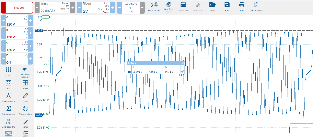
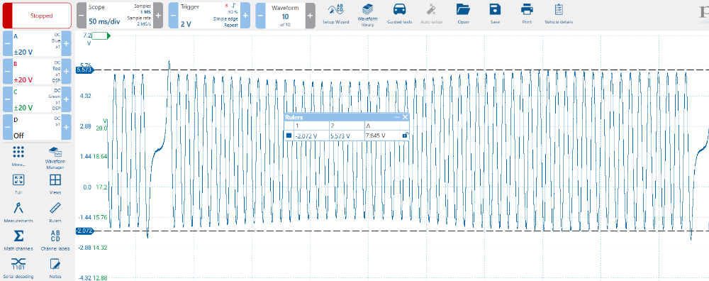 Here are the waveform captures in Pico 7 automotive
Replied by btisher05 on topic Question about a waveform for a crankshaft position sensor
Please Log in or Create an account to join the conversation.
- Chad
-

- Offline
- Moderator
-

- I am not a parts changer.
Less
More
- Posts: 2199
- Thank you received: 741
10 months 6 days ago - 10 months 6 days ago #92218
by Chad
"Knowledge is a weapon. Arm yourself, well, before going to do battle."
"Understanding a question is half an answer."
I have learned more by being wrong, than I have by being right.")
Replied by Chad on topic Question about a waveform for a crankshaft position sensor
That is a Variable Reluctance Sensor. It creates its own AC voltage. The amount of voltage that is created depends on a few different factors.
One factor is the speed at which the engine is turning. The faster the engine speed, the higher the voltage that is produced.
Another factor is the air gap between the sensor and the reluctor/tone-ring. A wider air gap will produce less voltage than a narrower air gap.
Seeing the same high/low voltage pattern in both of your waveforms makes me suspect that your reluctor/tone-ring might be, slightly, bent. If the tone ring is bent, the air gap will be wider and narrower as the crank spins. That will affect the voltage that is produced.
In these waveforms, even though the amplitude of the waveform is not perfectly even, it is more than enough to pass the high/low threshold that the PCM is looking for, and it is not a problem.
However, when cranking, the engine speed is much slower and the voltage output of the sensor will be much lower, as well. If the voltage amplitude is too low to pass the high/low threshold that PCM is looking for, then the PCM will not see a crank signal.
"Knowledge is a weapon. Arm yourself, well, before going to do battle."
"Understanding a question is half an answer."
I have learned more by being wrong, than I have by being right.
Last edit: 10 months 6 days ago by Chad.
Please Log in or Create an account to join the conversation.
- btisher05
-
Topic Author
- Offline
- Junior Member
-
Less
More
- Posts: 20
- Thank you received: 0
10 months 3 days ago #92229
by btisher05
Replied by btisher05 on topic Question about a waveform for a crankshaft position sensor
Thank you for the insight. I haven't been able to duplicate the crank no start since replacing the CKPS but if it does occur again at least I have a direction to go in now. Would it do any good to try to take a look at the reluctor using a bore scope through the hole where the CKPS is mounted? Is the amount of deflection in this waveform bad enough that if the reluctor is bent or damaged in some other way would it be possible to see it or is this such a small amount that it wouldn't be worth the trouble?
Please Log in or Create an account to join the conversation.
- Tyler
-

- Offline
- Moderator
-
- Full time HACK since 2012
Less
More
- Posts: 6129
- Thank you received: 1544
10 months 2 days ago #92234
by Tyler
Replied by Tyler on topic Question about a waveform for a crankshaft position sensor
btisher05, I saw your after waveform and got a little curious about the changes in signal amplitude that you noted. Finding known good cam/crank waveforms for the 1.8L is tough, but I did find this example from a 1.6L on Rotkee:
rotkee.com/en/wavebase/good-timing-ckp-c...rand=181&engine=1865
I also found this known good from Kia service information for P0335 troubleshooting:
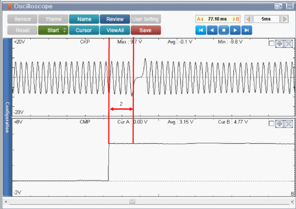
There's definitely some amplitude changes there, similar to yours.
rotkee.com/en/wavebase/good-timing-ckp-c...rand=181&engine=1865
I also found this known good from Kia service information for P0335 troubleshooting:
There's definitely some amplitude changes there, similar to yours.
Please Log in or Create an account to join the conversation.
- btisher05
-
Topic Author
- Offline
- Junior Member
-
Less
More
- Posts: 20
- Thank you received: 0
10 months 1 day ago #92239
by btisher05
Replied by btisher05 on topic Question about a waveform for a crankshaft position sensor
Thank you for the info that is good to know and helps to put my mind at ease that this fluctuation in amplitude is more than likely nothing to be overly concerned about.
Please Log in or Create an account to join the conversation.
Time to create page: 0.274 seconds