Moving the verticle position of the waveform on a Hantek 1008C
- SailorBob
-
 Topic Author
- Offline
- Elite Member
-

Is there a way in the Hantek 1008C software to bias the vertical position of the waveform on the screen so that zero volts is off the bottom of the screen?
Please Log in or Create an account to join the conversation.
- juergen.scholl
-

- Offline
- Platinum Member
-

- Active partschanger
- Posts: 1233
- Thank you received: 462
Other than that I don't think.
An expert is someone who knows each time more on each time less, until he finally knows absolutely everything about absolutely nothing.
Please Log in or Create an account to join the conversation.
- Andy.MacFadyen
-

- Offline
- Moderator
-

- Posts: 3357
- Thank you received: 1037
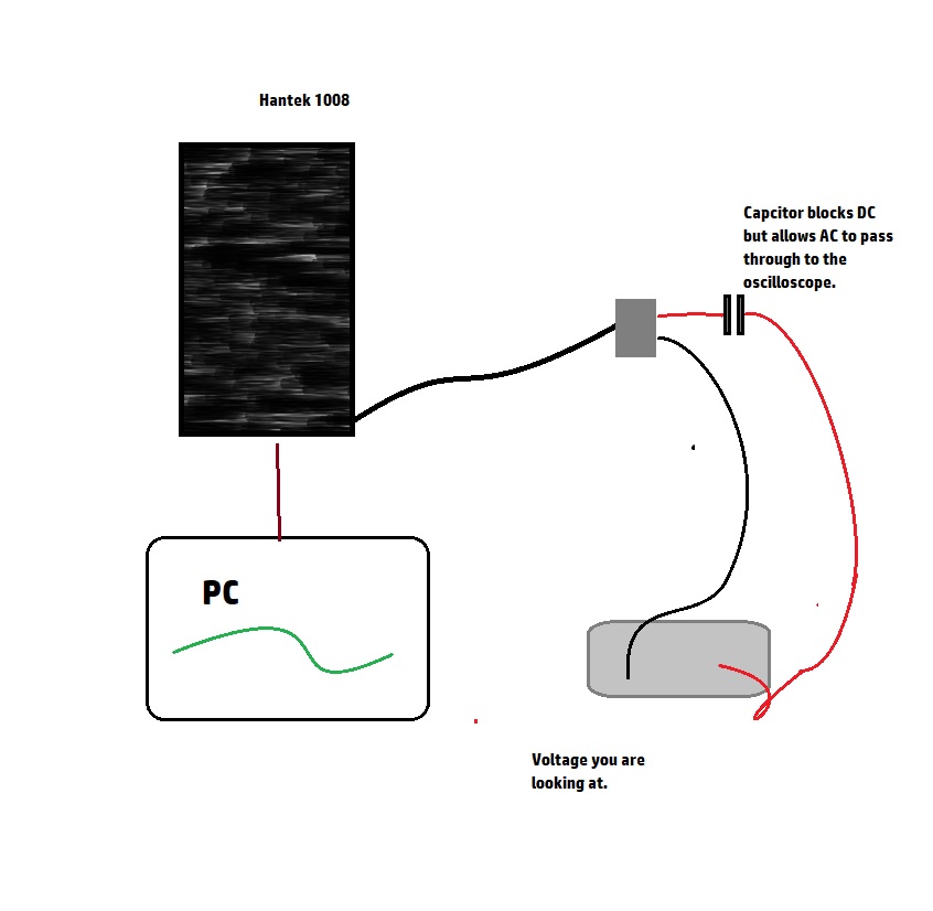
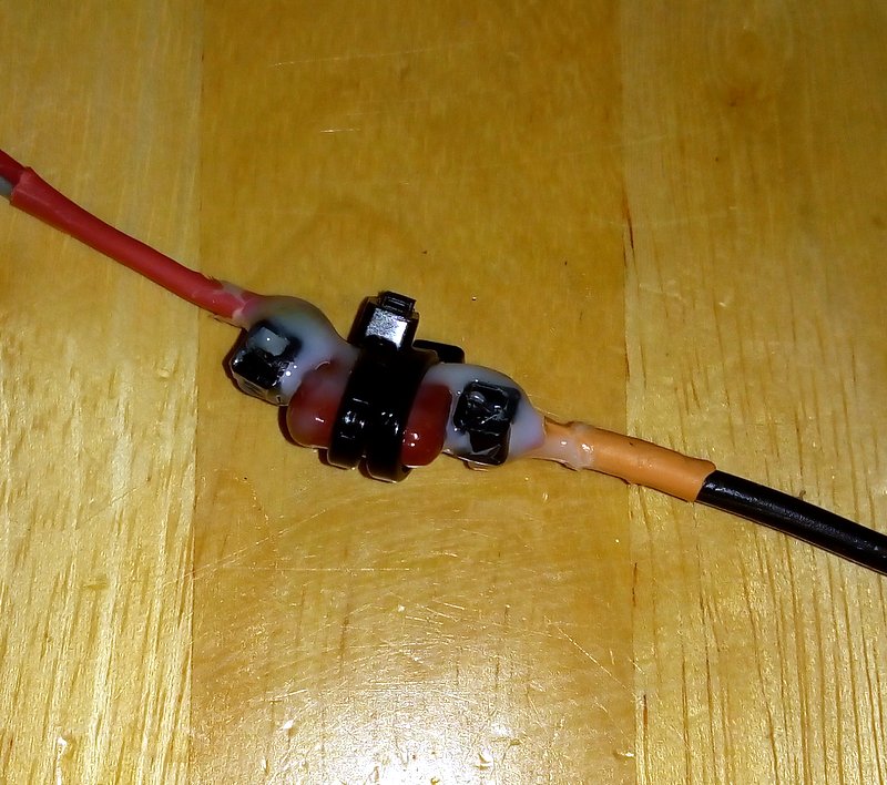
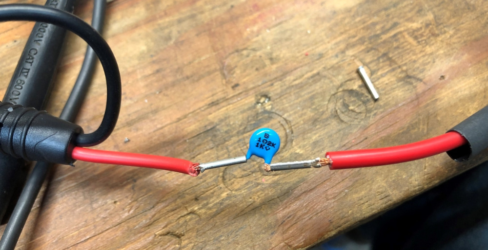
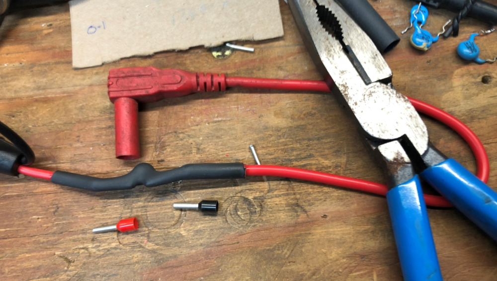
This is a really simple trick to do all you are really doing is putting a capacitor between the + wire of the scope and the voltage you are looking at. The capacitor blocks all the DC voltage part of the signal and leaves the AC wave form ---- good for cranking compression, alternator ripple and many other things.
I while back I posted a set of instructions on how to do this but I can't find the post it may have been in the old forum will I will look out for the pictures and spec of capacitor I used.
" We're trying to plug a hole in the universe, what are you doing ?. "
(Walter Bishop Fringe TV show)
Please Log in or Create an account to join the conversation.
- Andy.MacFadyen
-
- Offline
- Moderator
-
- Posts: 3357
- Thank you received: 1037
" We're trying to plug a hole in the universe, what are you doing ?. "
(Walter Bishop Fringe TV show)
Please Log in or Create an account to join the conversation.
- arbez
-

- Offline
- Premium Member
-

- Posts: 150
- Thank you received: 53
Andy.MacFadyen wrote:
That's ingenious.
Can you give some spec's on the capacitors requirements?
Do you have to be concerned with the capacitor charging up & zapping someone or something?
My scope does AC coupling, but I find this to be an interesting workaround if it didn't.
Thanks
Please Log in or Create an account to join the conversation.
- Andy.MacFadyen
-
- Offline
- Moderator
-
- Posts: 3357
- Thank you received: 1037
" We're trying to plug a hole in the universe, what are you doing ?. "
(Walter Bishop Fringe TV show)
Please Log in or Create an account to join the conversation.
- Andy.MacFadyen
-
- Offline
- Moderator
-
- Posts: 3357
- Thank you received: 1037
" We're trying to plug a hole in the universe, what are you doing ?. "
(Walter Bishop Fringe TV show)
Please Log in or Create an account to join the conversation.
- arbez
-
- Offline
- Premium Member
-
- Posts: 150
- Thank you received: 53
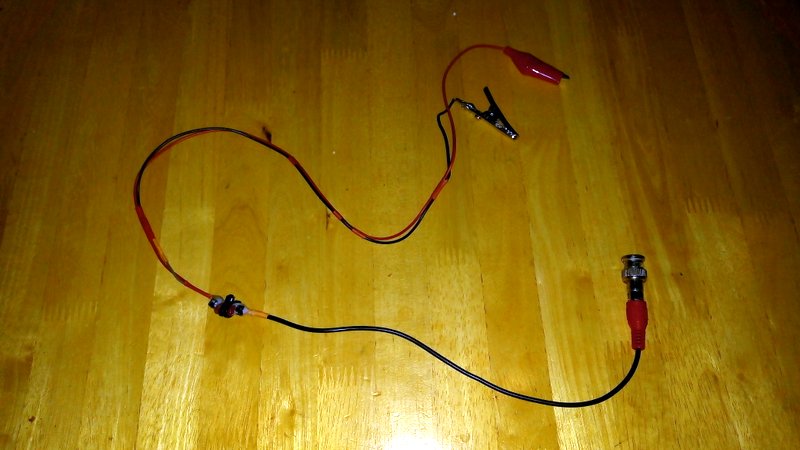
Inline banana adapter: www.aeswave.com/AC-Pass-Filter-Adapter-p9178.html
And a real nice insulated cable: www.aeswave.com/AC-Pass-Filter-Test-Lead-p8578.html
For $17.00, with free shipping, the banana adapter seems like the way to go.
Please Log in or Create an account to join the conversation.
- SailorBob
-
Topic Author
- Offline
- Elite Member
-
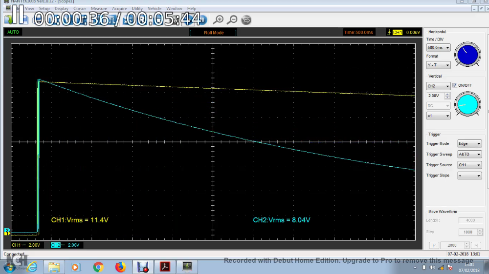
Then I tried a 0.1uF cap and it pulled down the voltage quite a bit quicker:
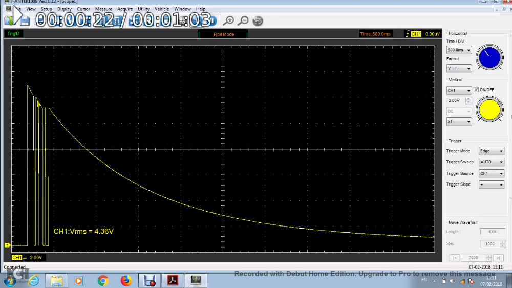
It still took about 10-15 seconds though, so in the future I'd probably use something allot smaller, like maybe a 0.01uF cap.
Still I got pretty good results using it on my alternator voltage which you can see here:
Please Log in or Create an account to join the conversation.
- SailorBob
-
Topic Author
- Offline
- Elite Member
-
autoditex.com/ac-coupling-adapter-100.html
There's a page on their site which lists local sales reps in various countries.
Please Log in or Create an account to join the conversation.
- SailorBob
-
Topic Author
- Offline
- Elite Member
-
Please Log in or Create an account to join the conversation.
- Matt T
-

- Offline
- Platinum Member
-
- Posts: 751
- Thank you received: 276
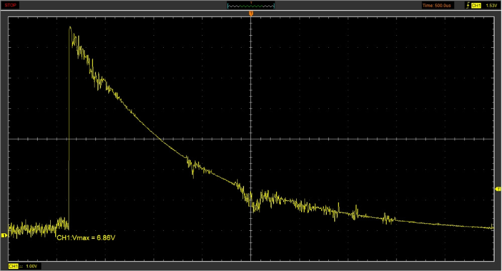
SailorBob wrote: It still took about 10-15 seconds though, so in the future I'd probably use something allot smaller, like maybe a 0.01uF cap.
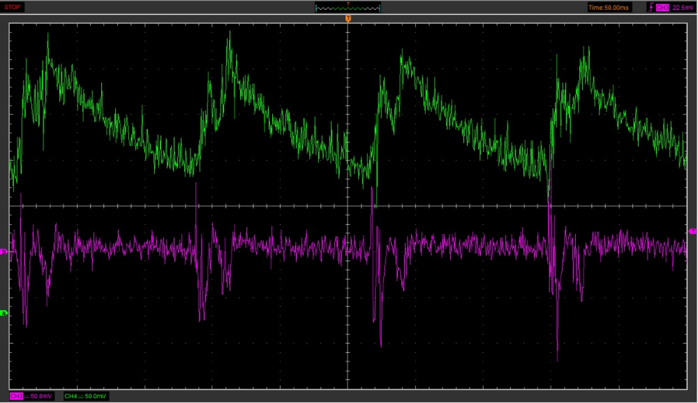
Going with the smaller is better theory I tried a 0.001uF I found in an old satellite receiver box. This was taken using a power supply set at 14v and the laptop plugged in. That's why the trace is noisy.
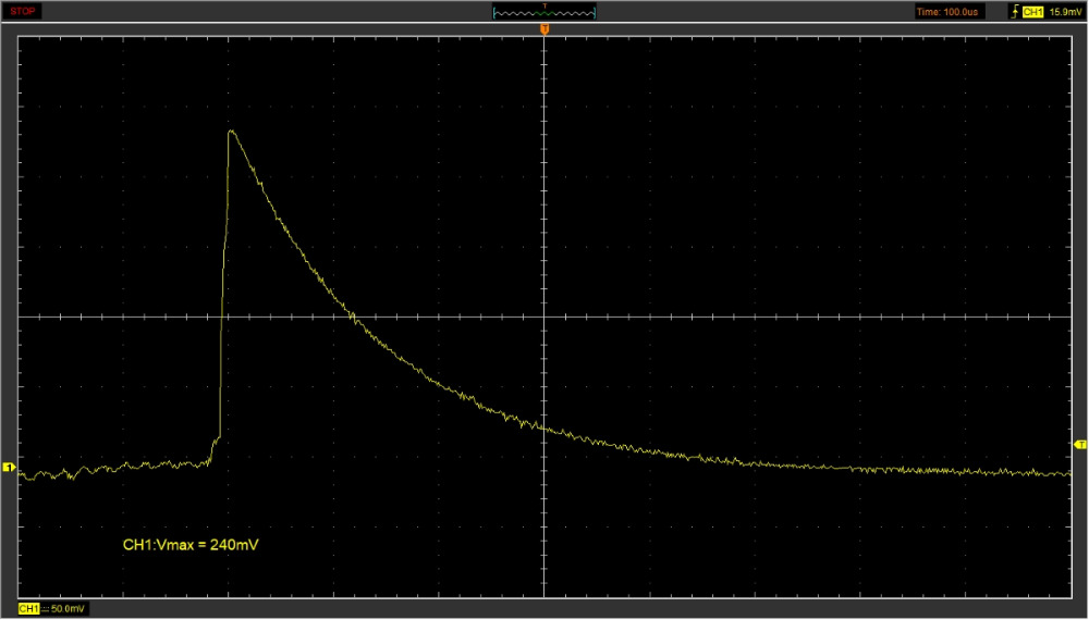
There was also a tiny 0.000068uF cap on the board so I tried it too. It really clamped the peak voltage and shortened the decay time. This one is using a battery as power source and with the laptop running on internal battery.
And this is what the laptop being plugged in was doing to the yellow AC coupled trace.
Please Log in or Create an account to join the conversation.
- Matt T
-
- Offline
- Platinum Member
-
- Posts: 751
- Thank you received: 276
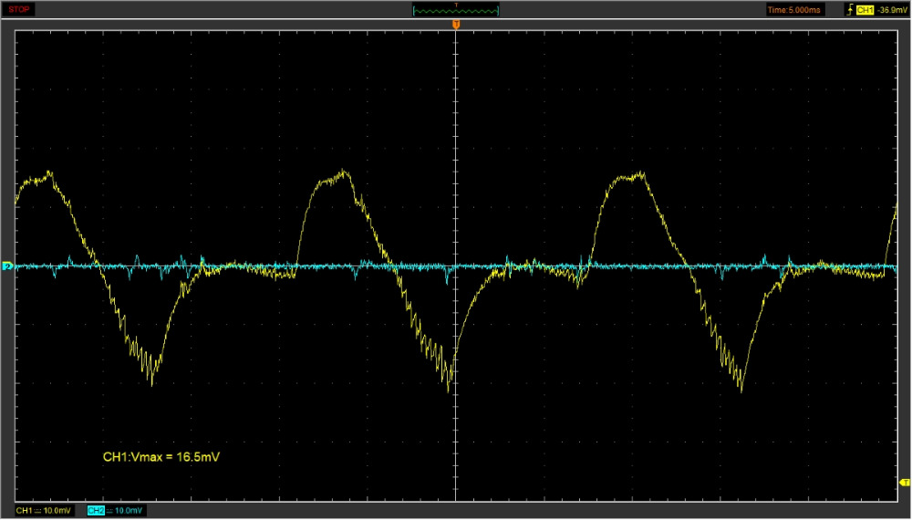
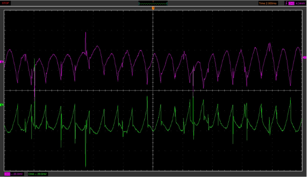
Now for testing. Purple traces are the AC coupled lead connected across the battery. Green are "current".
First off relative compression. Maybe this cap is too small to get a useable relative compression waveform??
Then I started the truck and got alternator ripple. The lead seems to be working really well for this test.
Please Log in or Create an account to join the conversation.