Crank and Cam signal wave interpretation
- forumoto
-
 Topic Author
- Offline
- Premium Member
-

- Christ De KING
now let say a physical sensor plate or reluctor plate and a camshaft reluctor,
now in the video, let say the person will show us, that this crank shaft reluctor or flex plate has this number of tooth’s, now when you watch from the video, you will see the wavefrom in this shapes , when you count from here to here, you will get this total of teeth, that when you bring it to reality you will get the number tooth on the reluctor. Now we will get that side , the next explanation should also be that, to determine cylinder, abc must be observe, counting from here or there, with example in the video. Now the same explanation should also go with cam signal, we need physical explanation and demonstration, some of us re not pro, we re beginners with handheld scopes and we want to really understand something. I have not seen no video that has explain things to detail, if someone know of any please share link. Thanks
Christ De Way Maker
Please Log in or Create an account to join the conversation.
- Chad
-

- Offline
- Moderator
-

- I am not a parts changer.
- Posts: 2196
- Thank you received: 738
That's a good question, worthy of an answer. I can't do a video but, I will try to explain the best that I can, verbally.how to know Which cylinder is number 1 and which 1 is 2 and etc. all the video online talks and explain things to us like we re a pro already. I would be grateful if someone can take his time and educate us the amateur, how to really interpret this signals, on a video with physical demonstration, that will be very good.
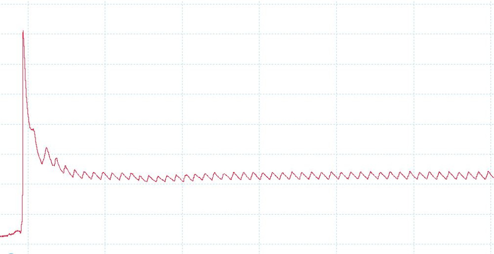
Here is a Relative Compression Waveform. Looking at this waveform, by itself, it is impossible to tell how many cylinders this engine has, let alone which cylinder is which.
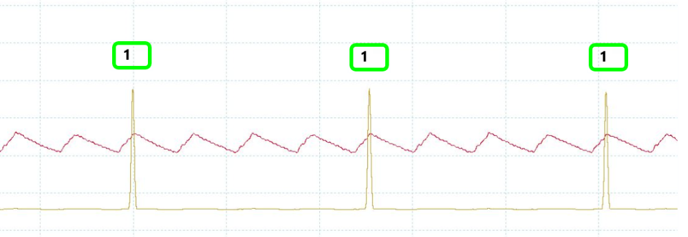
If we add a second yellow channel for an ignition strike on cylinder #1, we can now see that this is a 4-cylinder engine, with #1 spark plug firing in yellow.
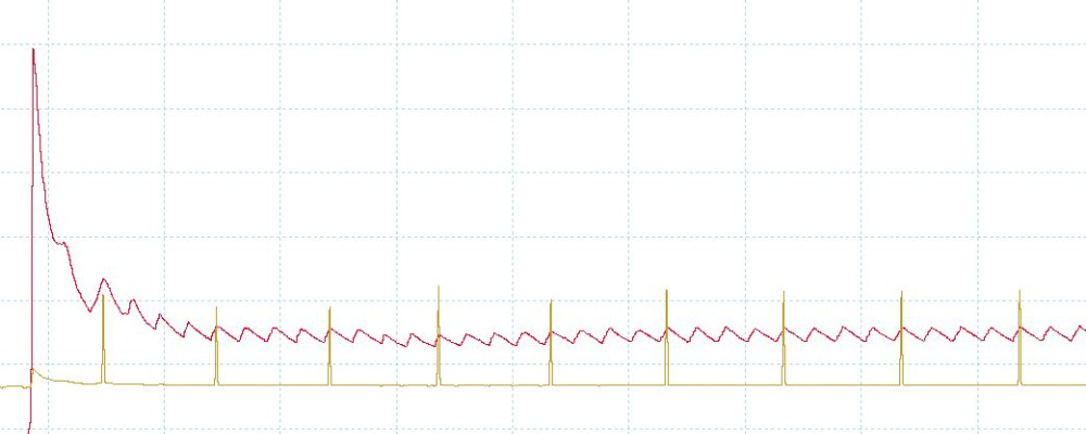
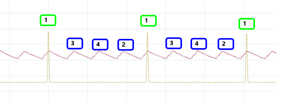
Now, all we have to do is plug in the firing order to identify the other cylinders.
I don't understand what you are asking.now let say a physical sensor plate or reluctor plate and a camshaft reluctor,
now in the video, let say the person will show us, that this crank shaft reluctor or flex plate has this number of tooth’s, now when you watch from the video, you will see the wavefrom in this shapes , when you count from here to here, you will get this total of teeth, that when you bring it to reality you will get the number tooth on the reluctor. Now we will get that side , the next explanation should also be that, to determine cylinder, abc must be observe, counting from here or there, with example in the video. Now the same explanation should also go with cam signal, we need physical explanation and demonstration
"Knowledge is a weapon. Arm yourself, well, before going to do battle."
"Understanding a question is half an answer."
I have learned more by being wrong, than I have by being right.
Please Log in or Create an account to join the conversation.
- oic5555
-

- Offline
- New Member
-

- Posts: 18
- Thank you received: 11
Hope this helps
Don
Please Log in or Create an account to join the conversation.
- oic5555
-
- Offline
- New Member
-
- Posts: 18
- Thank you received: 11
Don
Please Log in or Create an account to join the conversation.