A place to discuss hardware/software and diagnostic procedures
O2 sensor testing with scan tool
- bandrauto
-
 Topic Author
- Offline
- Junior Member
-

Less
More
- Posts: 24
- Thank you received: 1
5 years 6 months ago #45574
by bandrauto
O2 sensor testing with scan tool was created by bandrauto
hello all, this is probably a basic question, but i can not remember from a class we attended, there is a way to check proper O2 function with a scan tool. i believe it is watching the O2 voltage during acceleration then quickly taking your foot off the accelerator. can anyone enlighten me to this? i cant remember all the pids to be watching to test this way.
Please Log in or Create an account to join the conversation.
- Tutti57
-

- Offline
- Platinum Member
-

Less
More
- Posts: 1098
- Thank you received: 253
5 years 6 months ago #45593
by Tutti57
Replied by Tutti57 on topic Re:O2 sensor testing with scan tool
Usually I'll look at the front sensor on a scan tool to make sure, with a little rpms held, that it's oscillating from at least 200mv to 800mv. You can pull a vacuum line off and see if immediately drops down to low voltage and introduce propane into the intake to see if voltage rises.
You won't really be able to judge the speed of these events on a scan tool, but these tests will give you a good idea of the sensor is responding to changes in the mixture.
Paul has some great videos out there on o2 sensor testing for you to check out.
A/F sensors are a different animal but you should still be able to see changes in the voltage values on the scan tool by messing with the mixture. The changes move the voltage in the opposite direction though, and voltage doesn't oscillate, it just sees a change in mixture and more quickly goes back to it's base value. Tyler has a sticky in the diagnostic tools and techniques forum section on testing these sensors.
Nissan Tech
Please Log in or Create an account to join the conversation.
- Tyler
-

- Offline
- Moderator
-

- Full time HACK since 2012
Less
More
- Posts: 6129
- Thank you received: 1544
5 years 6 months ago #45598
by Tyler
Replied by Tyler on topic O2 sensor testing with scan tool
I think Andy calls it a 'dipsy doodle'? :silly: I can't remember exactly. I'll try to dig up his original post.
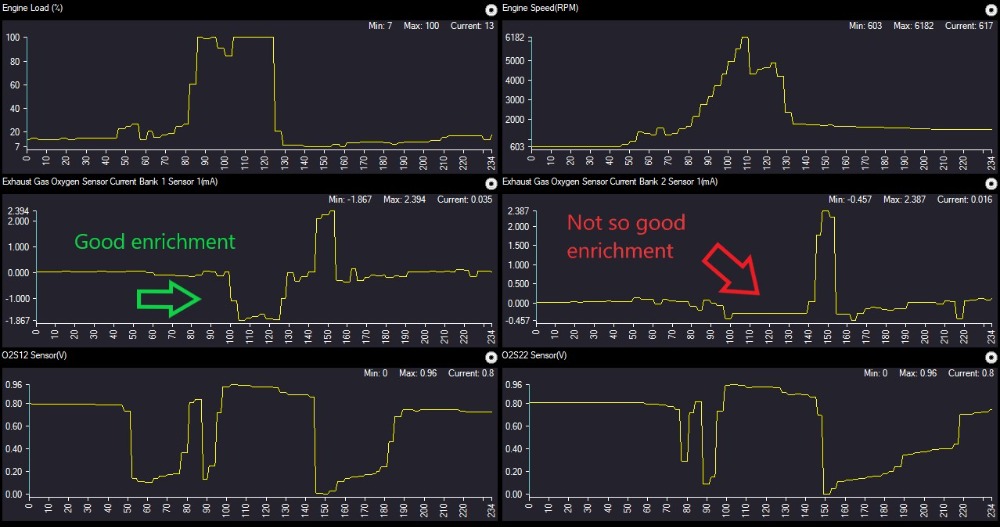
My go-to quick test for A/F sensors is pretty similar to what you're describing. Wide open, get to fuel enrichment (if the car uses it), then closed throttle decelerate until the fuel cut. This forces the A/F sensor through its entire sensing range.
I have an example from a 2011 Edge 3.5 EcoBoost. This engine uses A/F sensors upstream (which Ford calls UEGO's), and conventional O2's downstream. This shot shows wide open acceleration through first gear and into second, then a closed throttle decel:
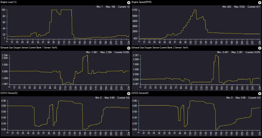
Ford A/F sensors show negative current flow to indicate rich, and positive current flow to indicate lean. Zero current indicates stoichiometric. I've included the downstream O2 signals as a reference.
This vehicle actually has a problem. Bank one upstream A/F goes quite rich during WOT, as most EcoBoost engine do. Bank two... doesn't. :lol: It flatlines at just under stoichiometric. However, both upstream A/F sensors achieve equal lean value during fuel cut.
My go-to quick test for A/F sensors is pretty similar to what you're describing. Wide open, get to fuel enrichment (if the car uses it), then closed throttle decelerate until the fuel cut. This forces the A/F sensor through its entire sensing range.
I have an example from a 2011 Edge 3.5 EcoBoost. This engine uses A/F sensors upstream (which Ford calls UEGO's), and conventional O2's downstream. This shot shows wide open acceleration through first gear and into second, then a closed throttle decel:
Ford A/F sensors show negative current flow to indicate rich, and positive current flow to indicate lean. Zero current indicates stoichiometric. I've included the downstream O2 signals as a reference.
This vehicle actually has a problem. Bank one upstream A/F goes quite rich during WOT, as most EcoBoost engine do. Bank two... doesn't. :lol: It flatlines at just under stoichiometric. However, both upstream A/F sensors achieve equal lean value during fuel cut.
The following user(s) said Thank You: Noah
Please Log in or Create an account to join the conversation.
- shootingchimp
-

- Offline
- New Member
-

Less
More
- Posts: 8
- Thank you received: 4
5 years 6 months ago #45603
by shootingchimp
Replied by shootingchimp on topic O2 sensor testing with scan tool
A good tip for broadband sensor testing with an Autel scan tool.
Graph the broadband O2 sensor ma/current pid. Open the drop box to adjust min and max settings. Start at -300 min and +300 max then fine tune for best results.
Your graph will now show the sensor response to fuel trim changes in a very similar way to a regular sensor with a 100mv to 900mv range. Except in ma as the sensor tries to balance it's internal measuring cell.
Please Log in or Create an account to join the conversation.
Time to create page: 0.215 seconds