Short Circuit Tool
- Tutti57
-
 Topic Author
- Offline
- Platinum Member
-

- Posts: 1098
- Thank you received: 253
last year and the instructor gave us these parts and a diagram to build this tool that you put in place of the fuse that keeps blowing. It lights up while the short is present so you can isolate it or do wiggle tests. The problem is that I lost the diagram and don't remember how to build it, ha. I remember you were supposed to get those GTC fuse things so you had a good way to plug it into the fuse place and add long wires to it so you can bring it in the car with you if needed. He also said that the yellow things were important but I don't know what they are. Some kind of capacitor I suspect, with xx30 UF400 on them. Does anyone have an idea of what I'm talking about here? I'm working on a short to ground now and thought this would be helpful.
Nissan Technician

Please Log in or Create an account to join the conversation.
- juergen.scholl
-

- Offline
- Platinum Member
-
- Active partschanger
- Posts: 1233
- Thank you received: 462
An expert is someone who knows each time more on each time less, until he finally knows absolutely everything about absolutely nothing.
Please Log in or Create an account to join the conversation.
- Matt T
-

- Offline
- Platinum Member
-
- Posts: 751
- Thank you received: 276
If the load is small enough, relative to the lamp, this also works with the load plugged in. My 100W test light will flow a 2A current without significant volt drop.
Please Log in or Create an account to join the conversation.
- Tyler
-

- Offline
- Moderator
-

- Full time HACK since 2012
- Posts: 6129
- Thank you received: 1544
www.aliexpress.com/item/32328262898.html
It's a pretty good idea for short circuit testing, especially combined with some kind of bulb to visually let you know if the fuse is open/closed/in the process of opening/whatever.
Please Log in or Create an account to join the conversation.
- Matt T
-
- Offline
- Platinum Member
-
- Posts: 751
- Thank you received: 276
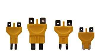
Tyler wrote: Those yellow doodads sure look like PTC fuses:
It's a pretty good idea for short circuit testing, especially combined with some kind of bulb to visually let you know if the fuse is open/closed/in the process of opening/whatever.
Good find. Wiring the PTC fuse and the lamp in parallel should make the lamp light when the fuse opens, so long as there is a path to ground on the load side.
Found a data sheet for these things. Looks like they take a while to trip, and also take time to reset. Good idea in theory but might not respond fast enough for wiggle testing??
www.littelfuse.com/~/media/electronics/d...rf_datasheet.pdf.pdf
Please Log in or Create an account to join the conversation.
- Tutti57
-
Topic Author
- Offline
- Platinum Member
-
- Posts: 1098
- Thank you received: 253
I got a chance to look at the car again today at work and found the short. I used a little different method than I have in the past. I pulled the fuse and used my power probe lights and sound to help find it. Power leg in the socket was power and the other side should have been nothing but was showing ground. At first it was a constant short so I turned the annoying sound off and watch for the green light to go off during the wiggle test. Then it changed to there not being a short so I turned the sound back on so it would make it when it came back. It worked well.
For those interested, it was a 2017 Rogue. Complaint was low oil pressure/shut off engine warning came on and engine turned off and wouldn't restart. It was short to ground on a TCM power wire. There is a golf ball sized harness that runs up along the left side of the valve cover and curves back around it. The harness rubs on a bolt there.
Nissan Technician
Please Log in or Create an account to join the conversation.
- Tyler
-
- Offline
- Moderator
-
- Full time HACK since 2012
- Posts: 6129
- Thank you received: 1544
Didn't know newer Nissan products would shut the engine off in response to a perceived low oil pressure condition...
Please Log in or Create an account to join the conversation.
- Tutti57
-
Topic Author
- Offline
- Platinum Member
-
- Posts: 1098
- Thank you received: 253
Nissan Technician
Please Log in or Create an account to join the conversation.
- Matt T
-
- Offline
- Platinum Member
-
- Posts: 751
- Thank you received: 276
Regards the "low oil pressure" I guess that was transmission oil pressure. Or have nissan powered the engine pressure transducer/switch from the TCM?
Please Log in or Create an account to join the conversation.
- Tyler
-
- Offline
- Moderator
-
- Full time HACK since 2012
- Posts: 6129
- Thank you received: 1544
Matt T wrote: Good thinking using the PP as a short finder.
I'm sitting here at home, and I can hear that Power Probe singing 'GROUNDDDDDDDDDDDDDDDDDDDDDDDDDDDDDDDDDDDDDDDDDDDD'
Please Log in or Create an account to join the conversation.
- Hardtopdr2
-
- Offline
- Platinum Member
-
- Posts: 853
- Thank you received: 150
Please Log in or Create an account to join the conversation.
- Tutti57
-
Topic Author
- Offline
- Platinum Member
-
- Posts: 1098
- Thank you received: 253

Nissan Technician
Please Log in or Create an account to join the conversation.
- Matt T
-
- Offline
- Platinum Member
-
- Posts: 751
- Thank you received: 276
Tutti57 wrote: I found the diagram! But, I don't understand how this would work in parallel with the bulb?
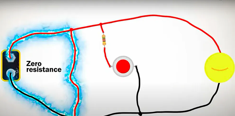
With the e-fuse closed the circuit is basically like this:
Power > e-fuse > Load > Ground. Voltage drop is mostly across the load so the bulb in parallel with the e-fuse isn't lit.
When a short opens the e-fuse the circuit changes to this:
Power > bulb > Ground. The bulb limits short circuit current and lights up to let you know the e-fuse has opened.
Please Log in or Create an account to join the conversation.
- Tutti57
-
Topic Author
- Offline
- Platinum Member
-
- Posts: 1098
- Thank you received: 253
Is that right?
Nissan Technician
Please Log in or Create an account to join the conversation.
- Matt T
-
- Offline
- Platinum Member
-
- Posts: 751
- Thank you received: 276
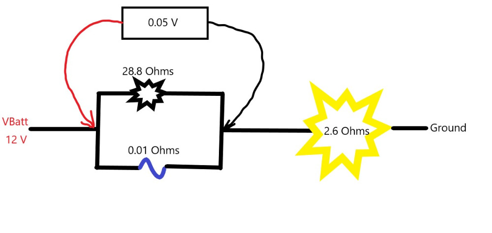
The indicator lamp is 5W and the load lamp is 55W in the following example. I've used hot resistances for them calculated from wattage. And I'm using the specs for a 10A e-fuse from the datasheet I linked earlier in the thread.
Here's the circuit under normal operation. The e-fuse and indicator lamp are the first resistance in a series resistance circuit with the load lamp being the second resistance.
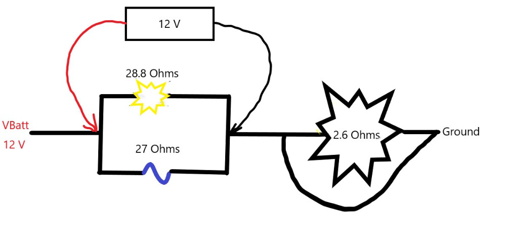
Now with the circuit shorted to ground you've got system voltage across both the indicator lamp and the e-fuse. Lights the lamp and trips the e-fuse. Total current limited to less than 1 amp.
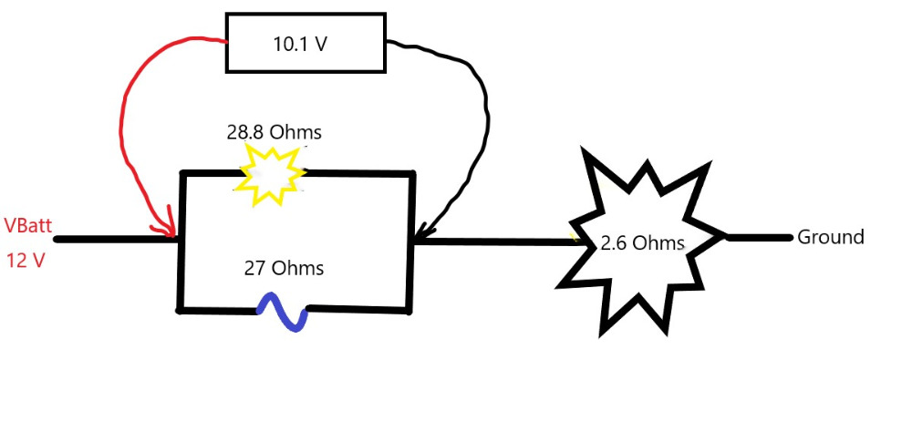
This is the tripped circuit with the short removed. Most of the volt drop is still across the indicator lamp and e-fuse. Indicator is still lit which is why I questioned how useful this device will be in the real world.
Please Log in or Create an account to join the conversation.
- amadjan22
-
- Offline
- New Member
-

- Posts: 1
- Thank you received: 1

Please Log in or Create an account to join the conversation.