A place to discuss hardware/software and diagnostic procedures
Testing Wheel Speed Sensors
- Charles Acosta
-
 Topic Author
- Offline
- Senior Member
-

Less
More
- Posts: 79
- Thank you received: 13
9 years 5 months ago #5267
by Charles Acosta
Testing Wheel Speed Sensors was created by Charles Acosta
Hello. The only way to learn these systems when I have time on my hands is to actually test the WSS on my 99 Mercury Mountaineer. I recently saw Paul's excellent video called Analog Speed Sensor Testing. So when the time came I decided to whip out the toys and play!
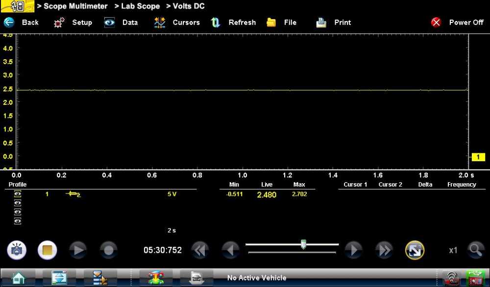
Connected at the Right Front WSS + and Black lead to BATT -

Connected at the WSS -
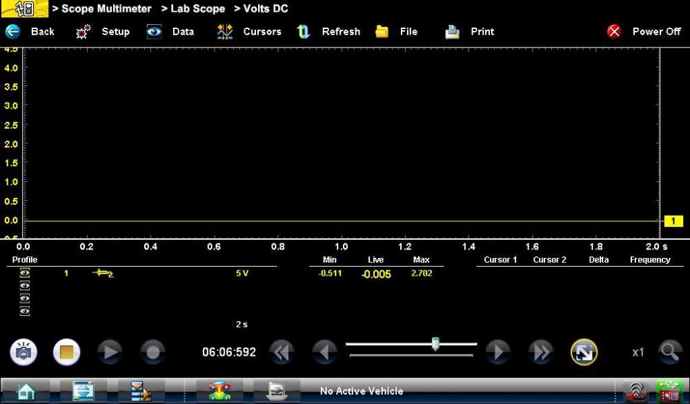
Sensor unplugged and Connected at the WSS -
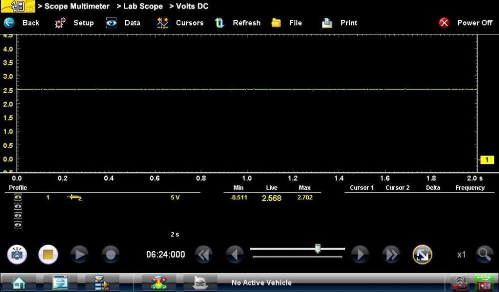
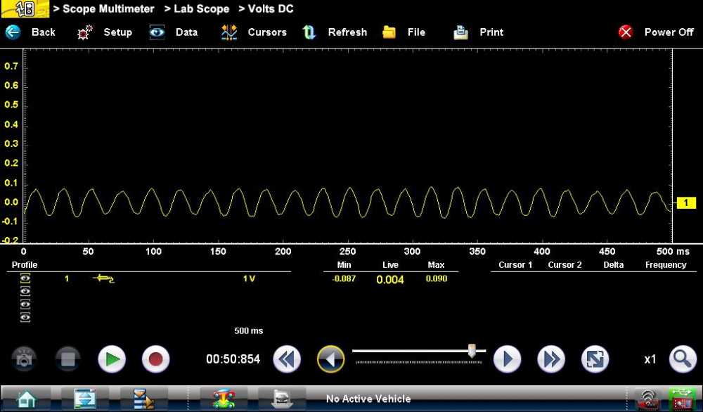
Sensor unplugged and Connected at the WSS+. This was odd. Just a .088 mv difference between plugged and unplugged. I believe this reading is the bias voltage. Did the same at the Left Front and it was identical.
Sensor plugged in. Connected at the Right Front WSS + and Black lead to BATT -
Connected at the WSS + and black lead to WSS -
So there it is. Hope I did this right. if not please chime in. Next i'll do the same testing on a 95 Nissan Maxima and post on this thread.
Connected at the Right Front WSS + and Black lead to BATT -
Connected at the WSS -
Sensor unplugged and Connected at the WSS -
Sensor unplugged and Connected at the WSS+. This was odd. Just a .088 mv difference between plugged and unplugged. I believe this reading is the bias voltage. Did the same at the Left Front and it was identical.
Sensor plugged in. Connected at the Right Front WSS + and Black lead to BATT -
Connected at the WSS + and black lead to WSS -
So there it is. Hope I did this right. if not please chime in. Next i'll do the same testing on a 95 Nissan Maxima and post on this thread.
Please Log in or Create an account to join the conversation.
- matt.white
-
- Offline
- Elite Member
-

Less
More
- Posts: 220
- Thank you received: 29
9 years 5 months ago #5276
by matt.white
Replied by matt.white on topic Testing Wheel Speed Sensors
Nice post Tribal. Vrs type sensors are still a bit mirky to me.
I hope it's ok to post here but it's very on topic. Saw this come up on a Facebook page. Definitely something to add to the wish list for me. An abs sensor tester as well as an emulator in one.
I hope it's ok to post here but it's very on topic. Saw this come up on a Facebook page. Definitely something to add to the wish list for me. An abs sensor tester as well as an emulator in one.
The following user(s) said Thank You: Charles Acosta
Please Log in or Create an account to join the conversation.
- Andy.MacFadyen
-

- Offline
- Moderator
-

Less
More
- Posts: 3357
- Thank you received: 1037
9 years 5 months ago - 9 years 5 months ago #5281
by Andy.MacFadyen
" We're trying to plug a hole in the universe, what are you doing ?. "
(Walter Bishop Fringe TV show)
Replied by Andy.MacFadyen on topic Testing Wheel Speed Sensors
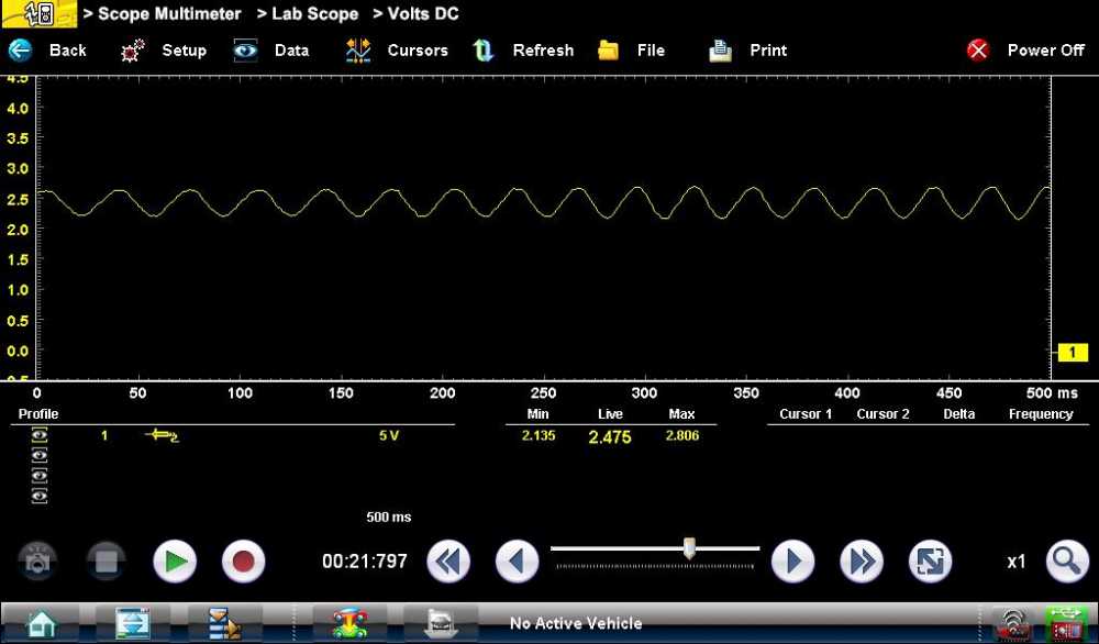
The bias voltage is there to allow the ABS module to check the continuity and integrity of the circuit before the vehicle actually moves. To do this the module actually measures the current through the circuit by looking at the voltage drop across a resistor integral to the module.
This type wheel speed sensor is very simple just coiled wire round a soft iron core, 19th century technology going back to the days of Michael Faraday and Thomas Edison.
As the toothed ring passes the sensor the varying magnetic field causes the coil of sensor to act as an AC generator. The AC voltage generated is superimposed over the DC bias voltage. Connecting a labscope in the normal DC coupling mode the AC voltage shows as a sine wave ripple sitting on top of the DC bias voltage. The AC ripple voltage generated by a particular sensor depends on the wheel rotation speed and air gap between the reluctor (tone) ring.
Faster rotation = more AC volts
Wider gap = less AC volts.
With a scope you can strip off DC bias voltage by switching the scope to AC coupling. Doing this makes it easier to read the Peak to Peak voltage and frequency of the signal.
With this type of wheel speed sensor I find 4 main types of fault.
(1) Splits in the toothed ring on the CV joint due to corrosion.
(2) Air gap is too large due corrosion causing AC voltage signal to drop out at low speed.
(3) Wiring corrosion and connector faults --- including the connector at the ABS module.
(4) Sensor failure.
With the scope you are essentially looking for a good consistant sine wave with no gaps or drop outs when the rotating each wheel at very low speed.
With these older style sensor to trace an ABS/Traction Control/Speedometer fault the best approach is usually looking at live sensor scan data graphed on screen looking for drop outs and low readings at slow speed.
Then a visual inspection the reluctor tone rings, sensors and wiring.
Then use the scope.
Keep in mind mis-matched tyre sizes, tyre pressures and wheel bearing problems can also cause "Implausible Signal" ABS fault codes to be logged.
" We're trying to plug a hole in the universe, what are you doing ?. "
(Walter Bishop Fringe TV show)
Last edit: 9 years 5 months ago by Andy.MacFadyen.
The following user(s) said Thank You: Tyler
Please Log in or Create an account to join the conversation.
Time to create page: 0.293 seconds