A place to discuss hardware/software and diagnostic procedures
Using Picoscope Automotive SepUps
- Batiscafo
-
 Topic Author
- Offline
- Senior Member
-

Less
More
- Posts: 43
- Thank you received: 9
6 years 3 months ago #37573
by Batiscafo
Using Picoscope Automotive SepUps was created by Batiscafo
I think I remember seeing one member post that suggested to use the Pico for Automóvil software in “Demo” mode to copy setUps and the if using like me a less expensive Pico hardware like my case with a 2205A, plug those numbers to start like if it was the Automotive hardware.
I have done it but I do not know what happens, but I can hardly get in signals to resemble the example signal “desired”
I imagine what many techs are suffering to get any results because they cannot get useful results in a reasonable time.
Some members here are a wealth of information, but is hard to find good information that is to the point and organized, and can be easily found with search.
Is there here in this Forum something like an index of “sticky” posts that we can make use of to maximize time spend?
Also: while scoping the primary voltage as learning alternative with the Pico 2205A I get a signal that is not even close no matter what I change. Now if I tried the trigger as: ETS Eureka the signals comes very close to the “desired” signal.
How in earth can a “compilation” of crappy signals change so much?
Appreciate very much some of the Huge efforts of some members that have spent hours for example to show step by step with pictures how to create new PROBES for my Pico hardware.
Thanks
Please Log in or Create an account to join the conversation.
- Paul P.
-

- Offline
- Platinum Member
-

Less
More
- Posts: 457
- Thank you received: 195
6 years 3 months ago - 6 years 2 months ago #37590
by Paul P.
Never stop Learning.
Replied by Paul P. on topic Using Picoscope Automotive SepUps
To use a 2205A, with the Automotive software, you'll need to install both programs, Picoscope 6 AND Picoscope 6 Automotive.
Navigate into the install directory of Picoscope 6, copy two .dll files PS2000.dll and PS2000a.dll.
Now, navigate to the Automotive version directory and paste these 2 .dll files.AND DELETE the OEM.DLL from the automotive directory!
Startup the Automotive version and you'll be able to connect the 2205A, it will now recognize it.
If you are probing the primary side of an ignition coil, I sure hope you are using an attenuator! or damage to the scope can result. 10:1 may not be enough for Primary Voltage due to the inductive spike. I use Hantek 20:1 attenuators.
These photos are Secondary Ignition with the HT-25.
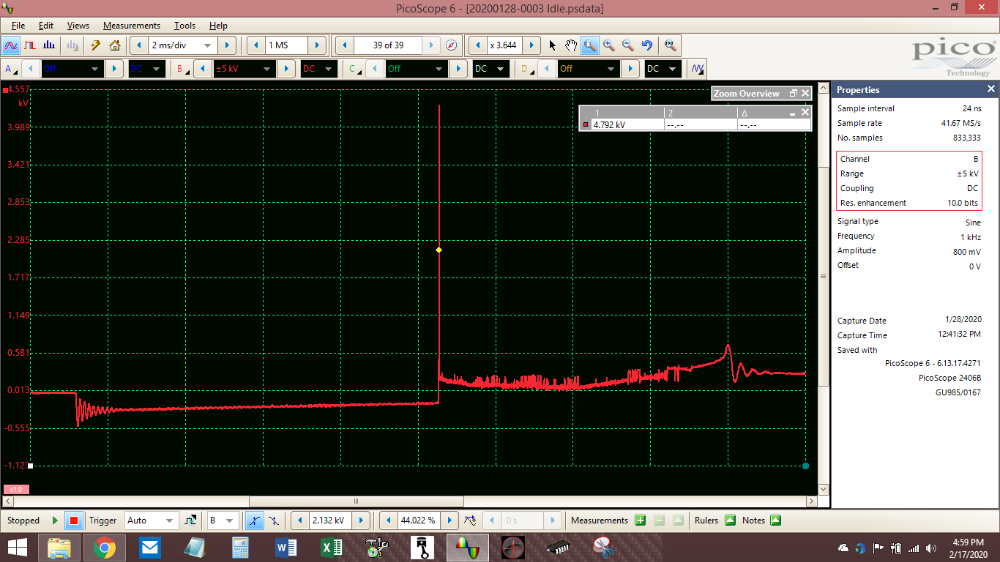
In this photo I'm am watching the spark occur with the motor running. Notice the time base 2ms and the sample rate 1MS, also there is a trigger to keep the waveform stabilized.
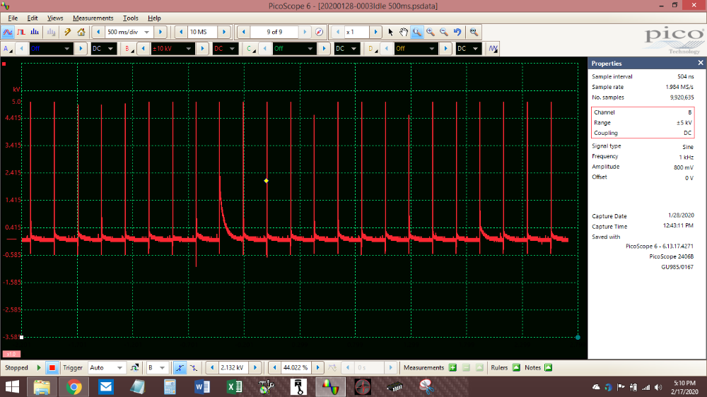
In this photo I have more time on the screen (500ms, the scope is in STREAMING mode ) and increased the sample rate.
See the Spark that is 2 to the left of the trigger diamond? That spark occured outside of the combustion chamber(Cross-over). Here is the power of the Pico, in the next photo I'll ZOOM in and it will be 8-bit vertical Resolution, the next will be the same photo but with a little more resolution to clean it up!
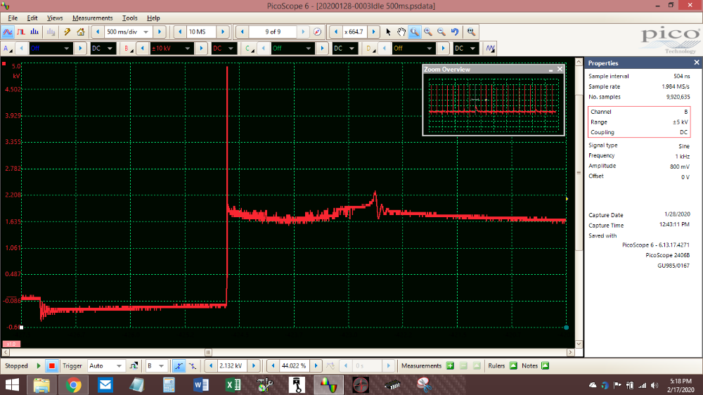
with 8-bit
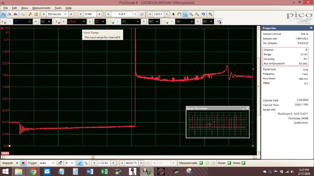
and now a little resolution enhancement
You can use the mouse scroll wheel to zoom in as well...

So as a general rule of thumb, when taking captures you want to see as they are occurring, use a smaller time base and a lower sample rate.
When using a longer time base 200ms and longer, you'll need to up the sample rate.
Paul
Navigate into the install directory of Picoscope 6, copy two .dll files PS2000.dll and PS2000a.dll.
Now, navigate to the Automotive version directory and paste these 2 .dll files.AND DELETE the OEM.DLL from the automotive directory!
Startup the Automotive version and you'll be able to connect the 2205A, it will now recognize it.
If you are probing the primary side of an ignition coil, I sure hope you are using an attenuator! or damage to the scope can result. 10:1 may not be enough for Primary Voltage due to the inductive spike. I use Hantek 20:1 attenuators.
These photos are Secondary Ignition with the HT-25.
In this photo I'm am watching the spark occur with the motor running. Notice the time base 2ms and the sample rate 1MS, also there is a trigger to keep the waveform stabilized.
In this photo I have more time on the screen (500ms, the scope is in STREAMING mode ) and increased the sample rate.
See the Spark that is 2 to the left of the trigger diamond? That spark occured outside of the combustion chamber(Cross-over). Here is the power of the Pico, in the next photo I'll ZOOM in and it will be 8-bit vertical Resolution, the next will be the same photo but with a little more resolution to clean it up!
with 8-bit
and now a little resolution enhancement
You can use the mouse scroll wheel to zoom in as well...
So as a general rule of thumb, when taking captures you want to see as they are occurring, use a smaller time base and a lower sample rate.
When using a longer time base 200ms and longer, you'll need to up the sample rate.
Paul
Never stop Learning.
Last edit: 6 years 2 months ago by Paul P.. Reason: missed a step, oopps!
The following user(s) said Thank You: Dylan, Dtech494, Batiscafo
Please Log in or Create an account to join the conversation.
- Dtech494
-
- Offline
- Junior Member
-

Less
More
- Posts: 35
- Thank you received: 9
6 years 1 month ago #38631
by Dtech494
Replied by Dtech494 on topic Using Picoscope Automotive SepUps
Thanks this work very nicely.
I had a different work around that you manually copy and save the preset files and start them up as a saved test. But this works much nicer.
I had a different work around that you manually copy and save the preset files and start them up as a saved test. But this works much nicer.
Please Log in or Create an account to join the conversation.
Time to create page: 0.272 seconds