New tool - A pulse sensor
- Deltron
-
 Topic Author
- Offline
- Senior Member
-

- Posts: 44
- Thank you received: 5
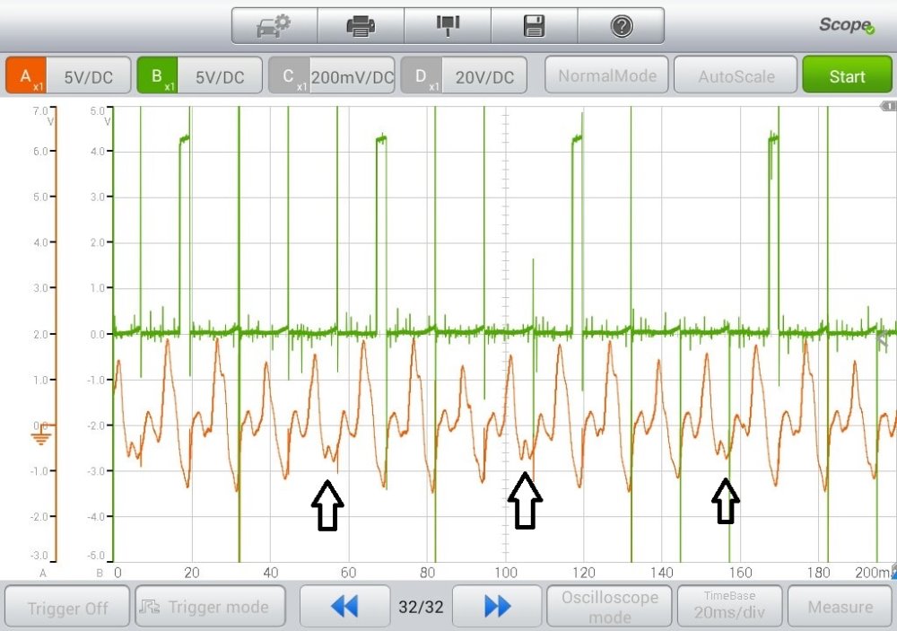
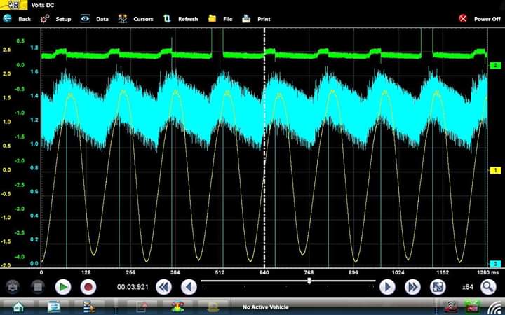
It doesn't give actual pressure or vacuum numbers, it simply shows pulses of either. Above 0 is pressure, below is vacuum. I hooked this sensor up to my car (2003 Accord 2.4L) on the brake booster vacuum hose, just as a testing scenario and to see how it works.
This is my K24A motor running at 2,000 RPM. Red trace is the pulse sensor, green trace is cyl #4 ignition command squarewave from PCM, to act as a sync. Firing order is 1-3-4-2. Sorry about the noise on that channel(but it sorta helps identify other cyl TDC)
I have added pointers to the thing I want to discuss. I believe I may have found an issue with my car, I'm just not 100% sure on how to read this sensors output.
If you follow the math, the problem area is occurring at the cyl #3 firing event. Being that it's an intake vacuum capture at that moment, it must be 180 degrees from #3(the next cylinder to fire), meaning the cylinder/valves producing that jagged vacuum pulse must be #4 , right?
Also, I'd love to hear any general input on the pattern as this is brand new to me, first use ever.
Please Log in or Create an account to join the conversation.
- Andy.MacFadyen
-

- Offline
- Moderator
-

- Posts: 3357
- Thank you received: 1037
Inlet Valves : 0.21-0.25mm (0.008-0.010in)
Exhaust Valves: 0.28-0.32mm (0.011-0.013in)
" We're trying to plug a hole in the universe, what are you doing ?. "
(Walter Bishop Fringe TV show)
Please Log in or Create an account to join the conversation.
- Paul P.
-

- Offline
- Platinum Member
-

- Posts: 457
- Thank you received: 195
Can you please perform this test over, except, do an engine cranking analysis, not engine running.
Use your exact same scope set-up, disable the fuel pump and crank away!
Please post the pic.
Thanks
Never stop Learning.
Please Log in or Create an account to join the conversation.
- Tyler
-

- Offline
- Moderator
-
- Full time HACK since 2012
- Posts: 6129
- Thank you received: 1545
I agree with Weycraze, redo the capture cranking and fuel disabled. Since it's a K24, disconnecting the injectors might be the easiest method. Running intake waveforms can be tough to decypher, due to events happening so quickly.
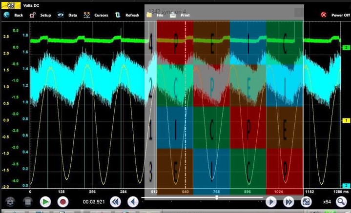
I threw an overlay up on your capture for clarity:
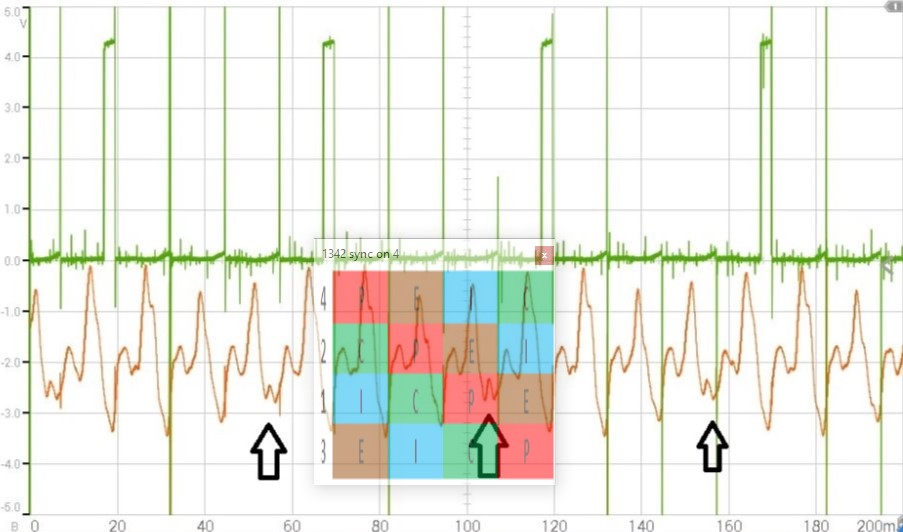
Sure looks like it's the #4 intake pull that's weaker than the others. Again, I wouldn't get too excited until you do a cranking capture.
Please Log in or Create an account to join the conversation.
- Deltron
-
Topic Author
- Offline
- Senior Member
-
- Posts: 44
- Thank you received: 5
Please Log in or Create an account to join the conversation.
- Paul P.
-
- Offline
- Platinum Member
-
- Posts: 457
- Thank you received: 195
driveabilityguys.com/software-and-tools .
I agree with Tyler, it does look like a weak pull on Cyl#4 Intake.
However, that can also be caused by a weak power stroke from companion #1 Cyl. ie, crank slowed down hence the weak pull.
Never stop Learning.
Please Log in or Create an account to join the conversation.
- Dylan
-

- Offline
- Moderator
-
- Belgium, Europe
- Posts: 1462
- Thank you received: 327
Tyler wrote: Congrats on the new tool! Who did you purchase from? I just recently got one from Cody's.
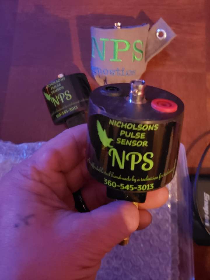
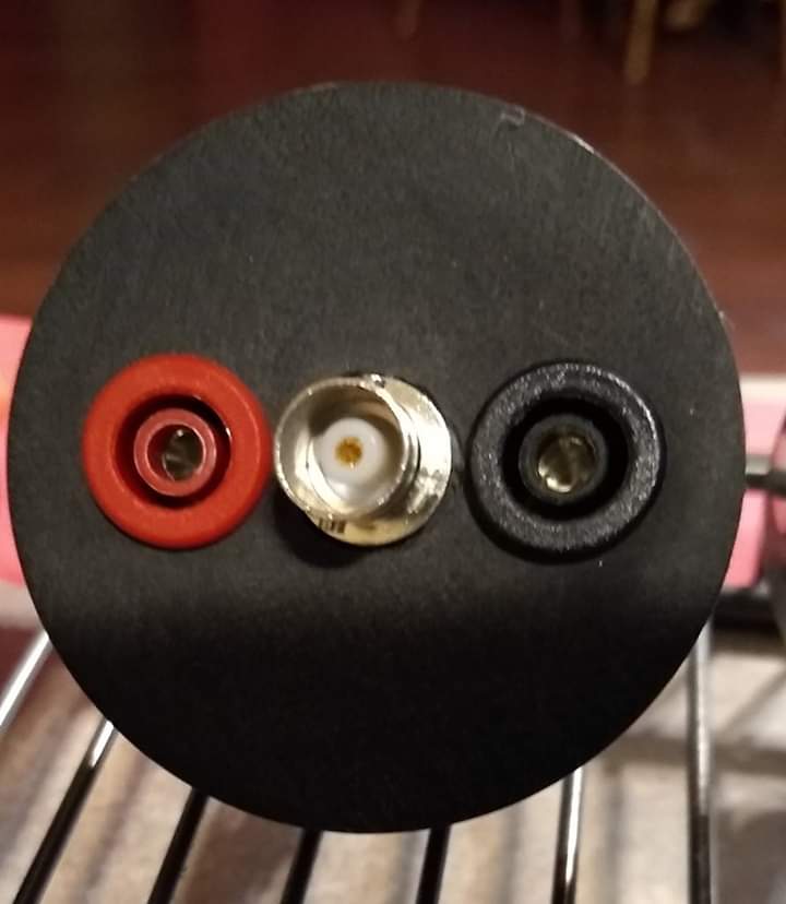
Cody does a great job. Nice guy. I recently saw that Michael Nicholson is making pulse sensors again. And not only with BNC but in combination with banana jacks. Think I might get one.
Please Log in or Create an account to join the conversation.
- Tyler
-
- Offline
- Moderator
-
- Full time HACK since 2012
- Posts: 6129
- Thank you received: 1545
Please Log in or Create an account to join the conversation.
- Michael N
-
- Offline
- New Member
-

- Posts: 3
- Thank you received: 3
Please Log in or Create an account to join the conversation.
- Michael N
-
- Offline
- New Member
-
- Posts: 3
- Thank you received: 3
I'm still pushing forward on building these. The gen3 is a more universal application for a verity of scopes.
Please Log in or Create an account to join the conversation.
- Deltron
-
Topic Author
- Offline
- Senior Member
-
- Posts: 44
- Thank you received: 5
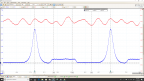
Take note that the "weaker" intake pull is now cyl #1 (sync is #4 again, 1-3-4-2)
You can see that on my original capture at 2k RPM, and the sawtooth pattern that I was concerned with seems to be an anomaly all it's own, and I'm wondering if it's actually a cylinder specific vtec problem.
Please Log in or Create an account to join the conversation.
- Tyler
-
- Offline
- Moderator
-
- Full time HACK since 2012
- Posts: 6129
- Thank you received: 1545
Please Log in or Create an account to join the conversation.
- Deltron
-
Topic Author
- Offline
- Senior Member
-
- Posts: 44
- Thank you received: 5
Please Log in or Create an account to join the conversation.
- Tyler
-
- Offline
- Moderator
-
- Full time HACK since 2012
- Posts: 6129
- Thank you received: 1545
Deltron wrote: I JUST got my overlay software and did that as you posted it, and you're right. It's 3 that's weak.
Sorry about that. :blush: I don't get to pull out my overlay as often as I'd like, so I get excited when I have an excuse!
Please Log in or Create an account to join the conversation.
- JarheadDiagnostics
-
- Offline
- New Member
-
- Posts: 18
- Thank you received: 11
Please Log in or Create an account to join the conversation.