A place to discuss hardware/software and diagnostic procedures
Secondary ignition sensor attenuation
- yodakubota
-
 Topic Author
- Offline
- New Member
-

Less
More
- Posts: 3
- Thank you received: 0
6 years 10 months ago #32937
by yodakubota
Secondary ignition sensor attenuation was created by yodakubota
I'm just getting started with teaching myself about ignition waveforms as a DIYer. I have a DS213 minidso scope and a Hantek HT25 secondary ignition sensor. This sensor is said to have a 10000:1 attentuation where the AESwave sensor is 1000:1. A review for the HT25 on Amazon suggested changing the capacitor in the sensor to adjust it to 1000:1 or 5000:1. I bought the HT25 because it was 1/3 the price and figured I'd give it a shot.
I was testing it on a lawn tractor this afternoon and was able to detect a waveform with the motor running. I'm assuming a lawn tractor makes the spark in the same or similar way a vehicle does? (If this is not a correct assumption, I will test it on a vehicle next.)
The waveform that was seen doesn't really look like what I've read it should look like. I realize the signal will be inverted on the scope. This scope has an Invert function for Channel 3 where it can be setup to display CH3 as the inverted waveform of either CH1 or CH2 (the analog channels.) However, using CH3 complicates setup so I didn't use it for this test.
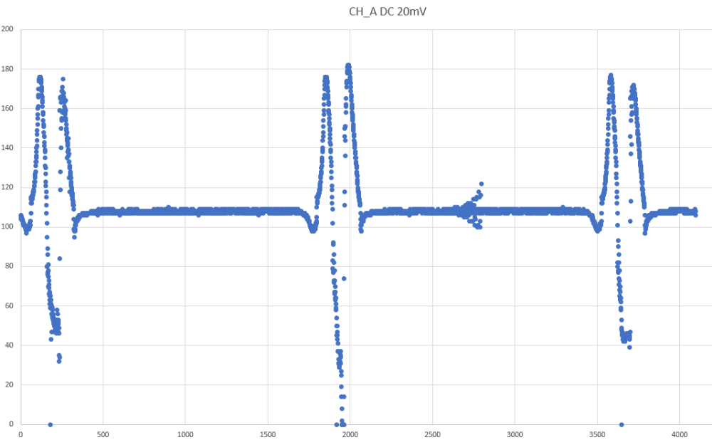
Here's a waveform made by the exported CSV data from the DS213 scope. The first two peaks on the left are at 171 according to the CSV file. The minimum is around 50. The channel A was set to DC 20mV according to the datafile with a timebase of 500uS. I'm pretty sure the 20mV is mV/Div. (Learning the new scope too. I've used bench scopes in school and at work; I'm getting used to how this scope handles things.)
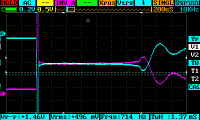
As an example of how this scope uses CH3 to invert the signal, I saved a BMP image. This was a capture during the testing on the lawn tractor, though it doesn't look like what I've read the waveforms should look like. Note, it's set for 50mV/Div with a 1mS timebase.
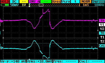
From reading about this online and through the Premium course, the time period that the spark is jumping the gap (for a car anyway) is 2-3mS, so I figured a 1mS timebase might be appropriate. Maybe it should have been set for longer? The 50mV/Div seemed to show the whole waveform, but I didn't see any really large peaks like I'd expect.
Could the 10000:1 attenuation be the problem here using it with the DS213? The DS213 is the upgraded version of the DS203. Similar to the uScope but two channel and 2 digital inputs. I really wanted a 2 input scope so I could learn how to correlate signals. There is a known bug I read about after purchasing that they're working on fixing but it's not fixed in the F/W yet. Something to do with triggering... minidso.com/forum.php?mod=viewthread&tid=3748&extra=page%3D1 and minidso.com/forum.php?mod=viewthread&tid=3339&extra=page%3D1
Maybe this bug isn't the issue. Maybe it's the sensor? Or a lawn tractor engine works differently than a car engine with the coils? This is a nifty scope for the price and it's pocket-portable. I'd like to try out a Picoscope and be able to scroll through the waveform capture and use the automotive preset features in their software, but the scope's a bit pricey for me experimenting at home, and I'd have to buy a laptop. (I'm still a desktop-holdout user!)
I was testing it on a lawn tractor this afternoon and was able to detect a waveform with the motor running. I'm assuming a lawn tractor makes the spark in the same or similar way a vehicle does? (If this is not a correct assumption, I will test it on a vehicle next.)
The waveform that was seen doesn't really look like what I've read it should look like. I realize the signal will be inverted on the scope. This scope has an Invert function for Channel 3 where it can be setup to display CH3 as the inverted waveform of either CH1 or CH2 (the analog channels.) However, using CH3 complicates setup so I didn't use it for this test.
Here's a waveform made by the exported CSV data from the DS213 scope. The first two peaks on the left are at 171 according to the CSV file. The minimum is around 50. The channel A was set to DC 20mV according to the datafile with a timebase of 500uS. I'm pretty sure the 20mV is mV/Div. (Learning the new scope too. I've used bench scopes in school and at work; I'm getting used to how this scope handles things.)
As an example of how this scope uses CH3 to invert the signal, I saved a BMP image. This was a capture during the testing on the lawn tractor, though it doesn't look like what I've read the waveforms should look like. Note, it's set for 50mV/Div with a 1mS timebase.
From reading about this online and through the Premium course, the time period that the spark is jumping the gap (for a car anyway) is 2-3mS, so I figured a 1mS timebase might be appropriate. Maybe it should have been set for longer? The 50mV/Div seemed to show the whole waveform, but I didn't see any really large peaks like I'd expect.
Could the 10000:1 attenuation be the problem here using it with the DS213? The DS213 is the upgraded version of the DS203. Similar to the uScope but two channel and 2 digital inputs. I really wanted a 2 input scope so I could learn how to correlate signals. There is a known bug I read about after purchasing that they're working on fixing but it's not fixed in the F/W yet. Something to do with triggering... minidso.com/forum.php?mod=viewthread&tid=3748&extra=page%3D1 and minidso.com/forum.php?mod=viewthread&tid=3339&extra=page%3D1
Maybe this bug isn't the issue. Maybe it's the sensor? Or a lawn tractor engine works differently than a car engine with the coils? This is a nifty scope for the price and it's pocket-portable. I'd like to try out a Picoscope and be able to scroll through the waveform capture and use the automotive preset features in their software, but the scope's a bit pricey for me experimenting at home, and I'd have to buy a laptop. (I'm still a desktop-holdout user!)
Please Log in or Create an account to join the conversation.
- Andy.MacFadyen
-

- Offline
- Moderator
-

Less
More
- Posts: 3357
- Thank you received: 1037
6 years 10 months ago - 6 years 10 months ago #32942
by Andy.MacFadyen
" We're trying to plug a hole in the universe, what are you doing ?. "
(Walter Bishop Fringe TV show)
Replied by Andy.MacFadyen on topic Secondary ignition sensor attenuation
Your lawn tractor will have a flywheel magneto ignition system the secondary voltage pattern will look very different from a conventional coil and battery system.
The general shape of the oscilloscope trace is similar to what I have seen from Briggs & Stratton lawnmower engines.
However you are pushing your oscilloscope beyond the limits of what it is best suited to do , you can see it is missing rapid changes in voltage.
I would leave the internals of the HT-25 be a car or even a lawnmore ignition can generate 50kv --- devided by 10,000 that gives 5v which is ideal for any oscillscope to show on a 10v screen
" We're trying to plug a hole in the universe, what are you doing ?. "
(Walter Bishop Fringe TV show)
Last edit: 6 years 10 months ago by Andy.MacFadyen.
Please Log in or Create an account to join the conversation.
- yodakubota
-
Topic Author
- Offline
- New Member
-
Less
More
- Posts: 3
- Thank you received: 0
6 years 10 months ago #32998
by yodakubota
Replied by yodakubota on topic Secondary ignition sensor attenuation
Thanks! I was under the (wrong) assumption that the waveform for the spark in a lawn mower would be the same as that in a vehicle. Good to know it looks similar to what you've seen. This is a Kawasaki 2-cyl engine. I'll have to look into how these magneto ignition systems work.
What do you mean by it's pushing the scope beyond its limits? Where is the rapidly changing voltage that it's missing? Do you mean the small blip near the 2750 time mark in the Excel plot, or is there something I should look for in the scope's image? The waveform was bouncing around a lot when I took that image file. I tried adjusting the trigger to smooth it out a bit and it steadied the trace some but every now and then it would change a lot from what it was.
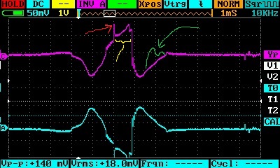
In the edited image above:
Are these the reasons why the scope is being pushed to its limit? e.g. It's not capturing everything? The scope generates a MHz square wave that it seems to be able to pick up. Maybe I'll bring it to work and test it with a function generator that is known to be accurate.
I thought this DS213 was supposedly faster than the version the uScope uses (DS201). I was assuming that if the uScope can see it, this one could; just that this scope wouldn't have the built-in presets and conversions. Maybe I made the wrong choice in choosing the DS213 mini dso... I really wanted two channels.
If the lawn mower (or car) can generate a 50kV signal, maybe I was looking at the wrong part of the waveform since I had it set to 20 or 50 mV/Div. I seem to only be seeing a ~150mV change in the signal. I initially thought I should have it set to 1V/Div based on the 10000:1 ratio and that the actual voltage could be 30-50kV, but I didn't see anything on the scope when it was set to 1V/Div. Maybe I had something else not quite set right. I'll try it again when I get a chance this week.
I'll try the scope on my car to see if that makes a difference. I've found waveform examples for cars but not mowers, so maybe I'm looking for the wrong thing with the mower. The mower was just easier to start and play with at the time. I'll try my car to see if I can see what I've been reading about.
Thanks for all the feedback!
What do you mean by it's pushing the scope beyond its limits? Where is the rapidly changing voltage that it's missing? Do you mean the small blip near the 2750 time mark in the Excel plot, or is there something I should look for in the scope's image? The waveform was bouncing around a lot when I took that image file. I tried adjusting the trigger to smooth it out a bit and it steadied the trace some but every now and then it would change a lot from what it was.
In the edited image above:
- Is the sharp spike increase where the red arrow is pointing the point at which the coil fires and creates the spark?
- Is the section of the traced marked by the yellow showing the spark's firing line and the time the spark is bridging the plug gap?
- Should the signal be seen to oscillate like shown in green?
Are these the reasons why the scope is being pushed to its limit? e.g. It's not capturing everything? The scope generates a MHz square wave that it seems to be able to pick up. Maybe I'll bring it to work and test it with a function generator that is known to be accurate.
I thought this DS213 was supposedly faster than the version the uScope uses (DS201). I was assuming that if the uScope can see it, this one could; just that this scope wouldn't have the built-in presets and conversions. Maybe I made the wrong choice in choosing the DS213 mini dso... I really wanted two channels.
If the lawn mower (or car) can generate a 50kV signal, maybe I was looking at the wrong part of the waveform since I had it set to 20 or 50 mV/Div. I seem to only be seeing a ~150mV change in the signal. I initially thought I should have it set to 1V/Div based on the 10000:1 ratio and that the actual voltage could be 30-50kV, but I didn't see anything on the scope when it was set to 1V/Div. Maybe I had something else not quite set right. I'll try it again when I get a chance this week.
I'll try the scope on my car to see if that makes a difference. I've found waveform examples for cars but not mowers, so maybe I'm looking for the wrong thing with the mower. The mower was just easier to start and play with at the time. I'll try my car to see if I can see what I've been reading about.
Thanks for all the feedback!
Please Log in or Create an account to join the conversation.
- Andy.MacFadyen
-
- Offline
- Moderator
-
Less
More
- Posts: 3357
- Thank you received: 1037
6 years 10 months ago - 6 years 10 months ago #33003
by Andy.MacFadyen
" We're trying to plug a hole in the universe, what are you doing ?. "
(Walter Bishop Fringe TV show)
Replied by Andy.MacFadyen on topic Secondary ignition sensor attenuation
The low end chinese scope manufacturers always greatly over claim the performance of the scopes they make devide it by at least 4 and then devide it by the number of channels. If you look at the CSV data plot you will see huge gaps where the scope just can't keep up with rapid changes in voltage.
Flywheel magnetos are very different from the classic automotive kettering coil and battery system.
A couple of links
aomci.org/forums/topic/ac-or-dc/
home.howstuffworks.com/chainsaw5.htm
Flywheel magnetos are very different from the classic automotive kettering coil and battery system.
A couple of links
aomci.org/forums/topic/ac-or-dc/
home.howstuffworks.com/chainsaw5.htm
" We're trying to plug a hole in the universe, what are you doing ?. "
(Walter Bishop Fringe TV show)
Last edit: 6 years 10 months ago by Andy.MacFadyen.
Please Log in or Create an account to join the conversation.
- yodakubota
-
Topic Author
- Offline
- New Member
-
Less
More
- Posts: 3
- Thank you received: 0
6 years 10 months ago #33118
by yodakubota
Replied by yodakubota on topic Secondary ignition sensor attenuation
I had time to take a look at a vehicle Friday evening. 8-cyl 5.8L Windsor. The waveforms look like what I've been reading about when measured on the spark cable from the coil to the distributor, though the voltage spikes at the firing line aren't as high as I would have thought. (Maybe this scope just isn't picking up the highest value like mentioned previously?) Also, I tried measuring waveforms on the plug wires that go between the distributor and each spark plug, but the waveforms didn't look like the ones below. I forgot to take a capture of those, but the waveforms were all over the place. I was only able to get a recognizable waveform by measuring the wire between the coil and the distributor...
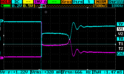
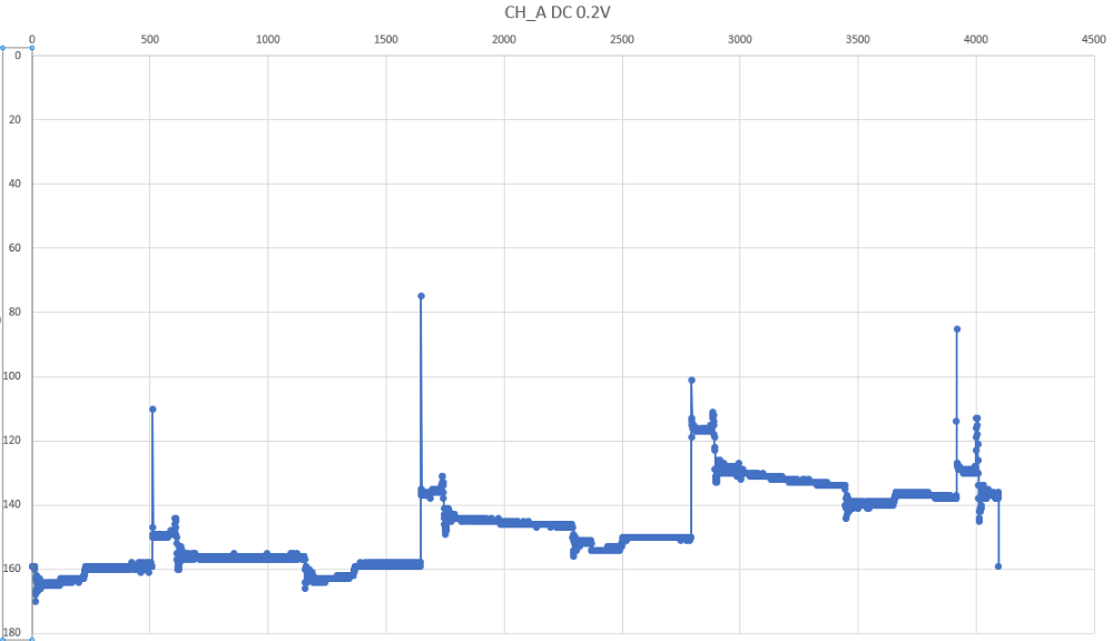
The voltage signal only changes by .7V on the 0.2V/Div scale in one image at 1mS timebase.
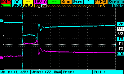
I believe this is the associated waveform data.
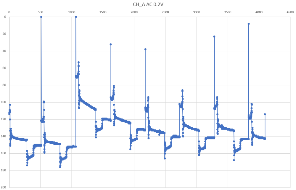
I captured another at 500uS timebase, 0.2V/Div
Here's the waveform data with the same timebase and volt Div settings:
This one was a fast timebase of 200uS. Looks like the spark time lasts for about 1.4mS (7 Divs @ 200uS/Div). 1.5mS seems reasonable? Again, I tried increasing the Volt/Div, but the scope wasn't detecting a large voltage spike, so the triggering didn't work very well when set at say 1V/Div.

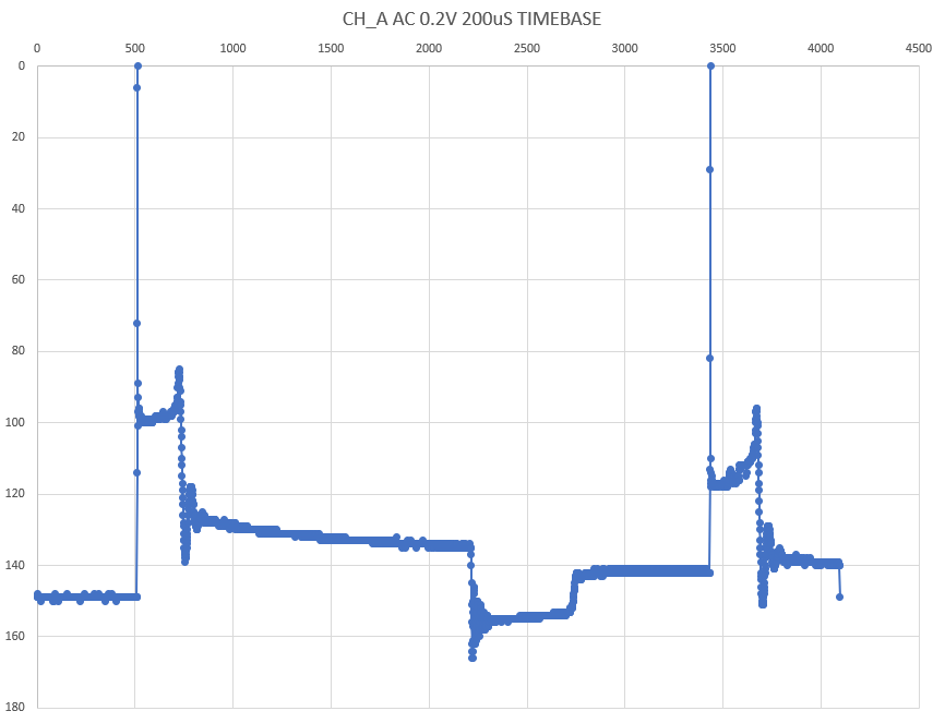
This 200uS timebase didn't show well on the screen, but the data plot seems to show one spark event pretty well. There's 4096 data points in each waveform datafile that was plotted in Excel. I've been reading more about bench scopes and many say they have 12-24 Mpts Memory depth. This 4096 looks like this is the "memory depth". One website says the DS213 has a 4k memory depth. With more memory depth, like 24 Million points offered in bench scopes, I gather I could measure at 200uS timebase and capture more spark events in the buffer.
*** Apologies here for transitioning this thread into a scope search topic. ***
I'm thinking I may need a faster scope with more memory depth to capture everything. I see two routes:
Models that might be good:
Rigol DS1054Z
Pros
Siglent SDS1104X-E
Pros
Picoscope 2206B 50 Mhz, 500 MS/s, 32Mpts memory, $350
Pros
Pico Auto 4225
Pros
It appears high bandwidth isn't as important for automotive as the pico auto scopes have 20Mhz BW. They have a massive memory depth. Is memory depth the most important? Having only 4K points now, I'd imagine 14-24 million on a bench scope would be HUGE improvement, let alone having 250 million. I guess this allows for fast sampling rates to be sure to capture more detail and fast spikes? But seeing high frequency signals isn't as important (only 20MHz). It seems like sampling rate and the buffer is where the DS213 falls apart.
The Pico Auto doesn't have as high of a sampling rate as single channel bench scopes above. It also has 12-bit instead of 8-bit. Is 12-bit important for catching spikes smoothly?
What is the recommended PC laptop specs for running Picoscope 6 or Pico Auto 6? The website suggests a processor speed greater than 2GHz, but doesn't give a processor minimum or recommendation. I was looking at budget 2 in 1 laptop/tablets like the ACER Spin 1 11.6" laptop w/ touch screen. It's under $300 refurbished, 4GB RAM running Win 10, 1080 HD display, 64GB storage, but has a 1.1 GHz Pentium N4200 quad core, but has a Burst Freq of 2.5 GHz. Is a Core i3 or i5 necessary to run the Pico software? I've built myself a couple desktops for gaming and productivity, but would rather not spend a lot on a PC that will be used in the garage.
From what I've seen on videos, the Pico auto looks really useful, but it's expensive for someone who's just starting to learn about things. Then again, I tried a cheaper route, and get confused simply because the scope isn't picking up enough signal. It's also confusing when learning and the instrument isn't showing what's needed...
I've read through the thread on choosing an intro scope a bunch of times, but just not sure which scope or path (bench vs. PC) to take at the moment considering costs along with the scope specs that I'd need to detect the signals I'm trying to look at...
The voltage signal only changes by .7V on the 0.2V/Div scale in one image at 1mS timebase.
I believe this is the associated waveform data.
I captured another at 500uS timebase, 0.2V/Div
Here's the waveform data with the same timebase and volt Div settings:
This one was a fast timebase of 200uS. Looks like the spark time lasts for about 1.4mS (7 Divs @ 200uS/Div). 1.5mS seems reasonable? Again, I tried increasing the Volt/Div, but the scope wasn't detecting a large voltage spike, so the triggering didn't work very well when set at say 1V/Div.
This 200uS timebase didn't show well on the screen, but the data plot seems to show one spark event pretty well. There's 4096 data points in each waveform datafile that was plotted in Excel. I've been reading more about bench scopes and many say they have 12-24 Mpts Memory depth. This 4096 looks like this is the "memory depth". One website says the DS213 has a 4k memory depth. With more memory depth, like 24 Million points offered in bench scopes, I gather I could measure at 200uS timebase and capture more spark events in the buffer.
*** Apologies here for transitioning this thread into a scope search topic. ***
I'm thinking I may need a faster scope with more memory depth to capture everything. I see two routes:
- get a bench scope
- get a Pico PC scope (not the automotive version as it's too expensive for me right now). Would require buying a laptop which adds to cost
Models that might be good:
Rigol DS1054Z
Pros
- 4-CH
- 100 MHz upgrade possible
- 1000MSa/s, degrades quickly with more channels
- 24M mem depth for 1CH, degrades quickly with more channels
- good reviews & support on web
- Mem depth and samples degrades with channels used, but has high 1ch mem depth
- no CAN decoding
- no mention of custom presets possible
- 6MSa/s for 4 channels, 12MSa/s for 2 channels used
Siglent SDS1104X-E
Pros
- 2 ADC, so has 1GSa/s for 1 or 2 channels used, memory depth of 14M for 1 or 2 channels used, and 7 for 4 channels
- does CAN decoding
- has probe preset options for Amps
- waveform update rate much faster @ 100,000/s
- History buffer 80K frames compared to Rigol's 60K frames
- Smaller single channel mem depth (14M vs 24M for Rigol 1054z
- More expensive than Rigol 1054z
Picoscope 2206B 50 Mhz, 500 MS/s, 32Mpts memory, $350
Pros
- easy viewing on PC
- well developed software
- CAN decoding with lots of other protocols
- math equations
- software can save custom probes
- lots of memory 80K waveforms/second
- needs laptop
- more expensive w/ slower sample rates than others
- 2CH, not 4CH
- low voltage input range
Pico Auto 4225
Pros
- huge memory
- high voltage input
- software tests
- 12-bit
- Expensive
- needs laptop PC
It appears high bandwidth isn't as important for automotive as the pico auto scopes have 20Mhz BW. They have a massive memory depth. Is memory depth the most important? Having only 4K points now, I'd imagine 14-24 million on a bench scope would be HUGE improvement, let alone having 250 million. I guess this allows for fast sampling rates to be sure to capture more detail and fast spikes? But seeing high frequency signals isn't as important (only 20MHz). It seems like sampling rate and the buffer is where the DS213 falls apart.
The Pico Auto doesn't have as high of a sampling rate as single channel bench scopes above. It also has 12-bit instead of 8-bit. Is 12-bit important for catching spikes smoothly?
What is the recommended PC laptop specs for running Picoscope 6 or Pico Auto 6? The website suggests a processor speed greater than 2GHz, but doesn't give a processor minimum or recommendation. I was looking at budget 2 in 1 laptop/tablets like the ACER Spin 1 11.6" laptop w/ touch screen. It's under $300 refurbished, 4GB RAM running Win 10, 1080 HD display, 64GB storage, but has a 1.1 GHz Pentium N4200 quad core, but has a Burst Freq of 2.5 GHz. Is a Core i3 or i5 necessary to run the Pico software? I've built myself a couple desktops for gaming and productivity, but would rather not spend a lot on a PC that will be used in the garage.
From what I've seen on videos, the Pico auto looks really useful, but it's expensive for someone who's just starting to learn about things. Then again, I tried a cheaper route, and get confused simply because the scope isn't picking up enough signal. It's also confusing when learning and the instrument isn't showing what's needed...
I've read through the thread on choosing an intro scope a bunch of times, but just not sure which scope or path (bench vs. PC) to take at the moment considering costs along with the scope specs that I'd need to detect the signals I'm trying to look at...
Please Log in or Create an account to join the conversation.
- Andy.MacFadyen
-
- Offline
- Moderator
-
Less
More
- Posts: 3357
- Thank you received: 1037
6 years 10 months ago #33163
by Andy.MacFadyen
" We're trying to plug a hole in the universe, what are you doing ?. "
(Walter Bishop Fringe TV show)
Replied by Andy.MacFadyen on topic Secondary ignition sensor attenuation
Because the coil is not connected directly to the spark engines with distributor ignitions show differently shaped traces when connected to the coil lead . The reason is that they have an additional gap between the rotor arm and the distributor cap that the spark has to jump. this has two main effects
(1) Because it is isolated from the coil by the spark gap between the rotor l and distributor cap connecting to the spark plug lead won't show changes in voltage in the coil secondary before the spark jumps.
(2) Because voltage is dropped across the gap between the rotor arm and the distrubtor cap the peak voltage and spark line on coil (king) lead will be higher than on the spark plug lead.
The usual way to look at a the secondary distributor ignition is to look at the train of firing events on king lead and use a separated probe on a plug lead to synchronize the trigger so the cylinders can be identified using firing order.
Using the probe on the king lead the trick is to identify a misfiring cylinder by looking for a cylinder that dosen't fit the pattern ---- As Jim Morton puts it look at the forrest but you are really looking for trees that don't fit in Normally this is done durring a throttle sanp as as the increase in gas pressure in the cylinder drives the required secondary voltage sky high.
Older cars tend to shorter spark duration which can be as low as 0.8 ms.
Spark plug voltage also tends to be lower on older vehicles because the spark plug gap is usually narrower and older non-multivalve engines tend to have lower compresion ratios.
With
" We're trying to plug a hole in the universe, what are you doing ?. "
(Walter Bishop Fringe TV show)
The following user(s) said Thank You: Noah, realxman
Please Log in or Create an account to join the conversation.
Time to create page: 0.264 seconds