Air/fuel ratio sensor testing thread
- Tyler
-
 Topic Author
- Offline
- Moderator
-

- Full time HACK since 2012
- Posts: 6129
- Thank you received: 1544
We’re all here to learn from each other, so I thought I share what I’ve gathered during my own diagnostics. I’ve tried to put this together in a way that’s easy to navigate, understandable for someone with zero wideband experience, and contains the kind of information I’d want to know if faced with a wideband sensor problem. Anyone looking for silver bullets should probably try elsewhere.
Before going further, you should definitely check out the links provided by lxuser about the internal construction of wideband sensors, how they differ from convention O2’s, and his own in-depth testing guide. These resources are far better at explaining wideband construction than anything I could put together :blush:
scannerdanner.com/forum/diagnostic-tools...sor-diagnostics.html
wbo2.com/lsu/lsuworks.htm
Common Themes
1.) Equivalence Ratio
As you'll see below, OEM's can vary widely in how they display the signal from their air/fuel ratio sensors. Some use current, others use an interpreted voltage... It can be tough to keep them straight!
If you're confused, remember that you can fall back on the Equivalence Ratio or Lambda PIDs. Equivalence Ratio is commonly provided on the Global OBD side (and some manufacturer data lists), while Lambda is usually seen on Honda models. Either way, 1.00 represents stoichiometric, with any values higher indicating lean, and lower indicating rich. This way, even if you knew jack squat about wideband sensors, you can still make sense of the data.
2.) Heaters are not optional
The majority of conventional O2’s are still capable of producing a decent signal with a blown heater element, provided the exhaust is hot enough. Not the case here. The heater HAS to be functioning, or the sensor will never work correctly. In fact, some vehicles will default to open loop fuel control with the presence of a heater fault.
3.) Rationality testing
Paul has repeatedly demonstrated the diagnostic value of comparing upstream and downstream sensors signals on the same bank to determine if a sensor is lying or not. Fortunately, the same idea still applies to wideband sensors! If you think you’ve got one that’s stuck rich or lean, don’t hesitate to take a glance at the downstream sensor and see if it agrees. I’ve found this to be the best way to catch lying sensors.
4.) Trim resistors and missing wires
Throughout this article, I’ll refer to sensor designs by the number of harness side wires, i.e. four, six, or seven wires. It’s important to note on the six and seven wire designs, you’ll actually only see five wires on the sensor side. Why? Trim resistors. See below:
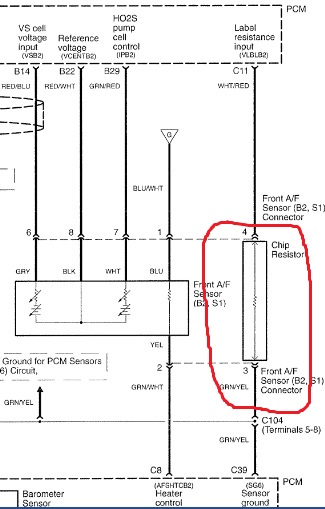
The trim resistor (AKA resistor chip) is integral to the wideband sensor connector (not the sensor itself), and is installed at the factory to allow the PCM to account for manufacturing tolerances. This resistance is measured by the PCM on a dedicated circuit, and can be installed parallel to the heater power OR sensor signal. Honda even goes so far as to have two wires dedicated for the resistor circuit on their seven wire designs.
Can trim resistors cause fuel control problems? To be honest, I’m not sure, as I’ve never seen it before. Anything’s possible!
Toyota/Lexus
Toyota and Lexus were one of earliest adopters of wideband sensors, and therefore the most likely to be encountered in the aftermarket. They’re also, IMO, the most failure prone. To my knowledge, this is the only type of wideband sensor Toyota uses.
If you haven’t seen it already, Paul did a fantastic two-part series on these sensors. Check it out!
-Scan data-
www.scanshare.io/share/9ps_DognO0u_ollTdSyNEQ#0,1,24,25,26,27
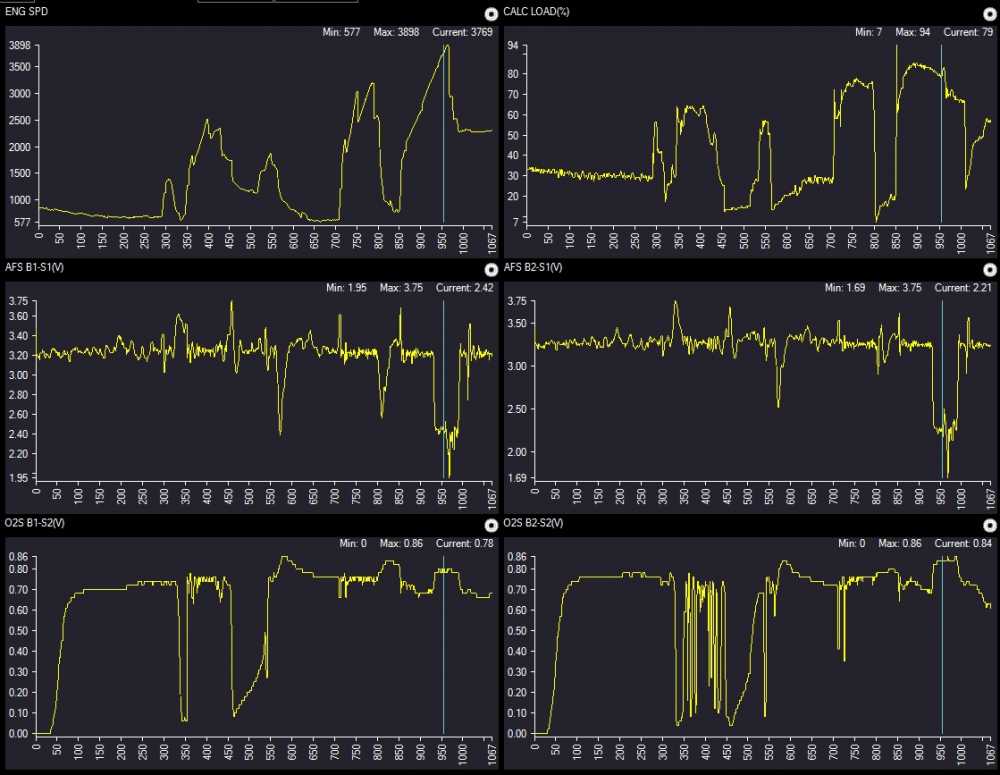
Scan data will show a voltage data PID associated with the A/F sensor signal. 3.3V represents stoich, lower indicates rich, and higher indicates lean. Seeing spikes in the data is not unusual during sudden changes in engine load.
It’s important to understand that, while the scan data displays the A/F sensor signal as a voltage, this is NOT the true sensor signal. The actual signal is a changing current, while the voltage at the sensor never changes. The A/F sensor data PID is merely an interpreted value based on the current signal.
Toyota sometimes provides a sensor current PID in mA, in addition to the voltage PID, but not always.
-Wiring checks-
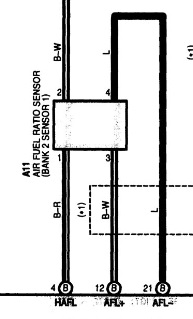
Wiring checks on these sensors are fantastically simple. Four wires, following the typical Bosch O2 sensor-side wire color format - the two wires colored alike are the heater circuit, the other two are for the sensor circuit.
Plugged in OR disconnected, you’ll find 3.3V on one sensor circuit wire (AFL+ on the diagram), and 2.9 - 3.0V on the other (AFL-). NEITHER will change significantly during mixture variations. 12V on one heater wire, and a computer controlled ground on the other, just like your typical heated O2’s.
The voltages seen on the two sensor circuit wires are provided from the PCM to the sensor connector, and therefore makes for easy circuit checks. If the above sensor circuit voltages are found at the connector, then the wiring is good!
Honda/Acura
The Honda four wire wideband sensor is VERY similar in design and operation to the Toyota sensor, most commonly found on their four cylinder engines. The V6’s usually get the seven wire sensor, which I’m not addressing just yet. Perhaps in the future!
-Scan data-
www.scanshare.io/share/ZsdIdUM6zkK47APTf-fFqw#0,2,3,4,5,42,43
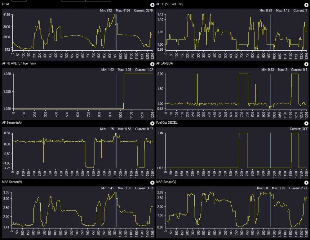
Honda will typically display the sensor current directly, no voltage conversion shenanigans. 0 mA represents stoich, negative current indicates lean, and positive current indicates rich. Have a close look at those current values: Around .4 mA during power enrichment, and 1.5 mA during fuel cut decel. This is why measuring the sensor signal directly is so difficult!
Note the AF FB and AF FB AVE PIDs - these are Honda-ese for short and long term fuel trims. Snap-On was kind enough to add the translation in, but I can’t say that all scanners will do this. They’re also not displayed like typical fuel trims, so remember this: Values above 1.00 represent positive trims, and values below 1.00 represent negative. For example, if your data showed AF FB at 1.13 and your AF FB AVE at .98, that would translate to a short term of 13% and a long term of -2%.
-Wiring checks-
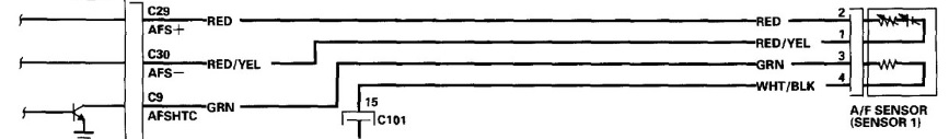
Circuit checks are almost identical to the Toyota sensor, with a similar Bosch sensor-side wiring color format, and similar wiring diagram designations. Plugged in or disconnected, you should find 2.2V on AFS+ and 1.8-1.9V on AFS-. Again, neither voltage should change significantly during typical operation. 12V feed for the heater, computer-controlled ground.
Like the Toyota sensor, this design makes it very easy to quickly verify circuit integrity, even without a wiring diagram.
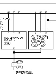
Nissan/Infiniti
To my knowledge, Nissan uses two designs of wideband sensors, four and six wire. I’ve usually found the four wire versions used with the 2.5L engine, with the six wire versions on V6 and V8 applications.
-Four wire scan data-
www.scanshare.io/share/acu6f1Lofk6YwAmKhhrDyw
The Nissan four wire sensor is another ‘current critical’ design that produces a current signal, but gets (mis)represented in scan data as a voltage. Again, this is smoke and mirrors - see Toyota wideband sensors above. 2.2V represents stoich, with over 4V seen on fuel cut decel, and 1.6V or less at WOT.
-Six wire scan data-
www.scanshare.io/share/RhcQ5whqU0mPCutDLNC56w#0,2,5,6,7,8
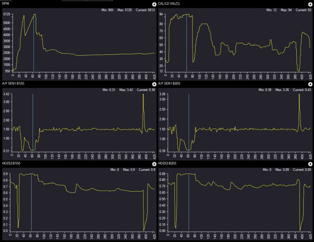
The six wire signal also uses a voltage signal PID, with 1.5V representing stoich this time. Another converted value… Why can’t OE’s treat us like adults? 3.00V or higher during fuel cut decel, and .7V or less during wide open power enrichment.
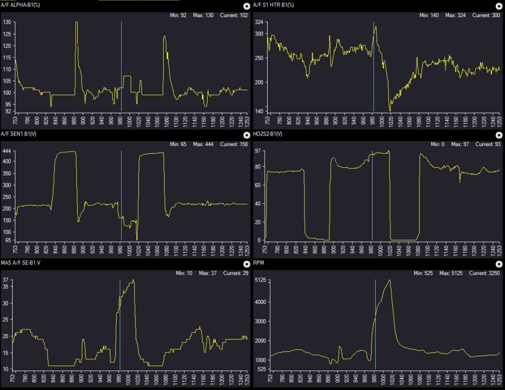
With both types (and conventional zirconia O2’s), Nissan has it’s own designation for short term fuel trims, ‘Alpha’, and they function just like the Honda AF FB PIDs. Values less than 1.00 are negative trims, greater than 1.00 are positive trims. I do occasionally see long term fuel trim PIDs in the scan data, but have NEVER seen them change or adapt to mixture problems. Take them with a grain of salt, IMO.
-Four wire wiring checks-
Checking this sensor is so similar to the Honda and Toyota sensors, I can’t help but think they’re all made by the same manufacturer. Bosch sensor-side wire colors, as usual.
Note the shield around pins 1 and 2 - dead giveaway that these wires are the signal circuit. Look for 2.2V on one, and 1.8V on the other. Just like the other four wire sensors, neither voltage will change significantly with the sensor unplugged or during mixture changes. Heater power and ground on pins 3 and 4.
-Six wire wiring checks-
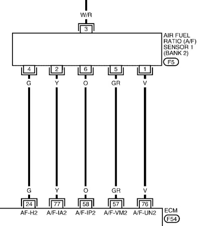
All voltage values described here will be from the harness side, with the scope/meter connected to battery ground. You’re probably thinking, “Duh!”, but some test procedures will have you connected to the sensors floating ground instead. If you choose to do this, just subtract 2.5V from all values below.
Unlike the four wire sensors we’ve covered, the Nissan six wire sensor voltage values WILL change during mixture variations, and if the sensor is plugged in or unplugged. For that reason, I’ll make the distinction between plugged in and unplugged below. Refer to the above diagram for pin numbers.
Plugged in:
Pin 1 (Sensor input) = 3.00V
Pin 2 (Sensor signal) = 2.5V at stoich, varies +/- 1.0V with mixture
Pin 3 (Heater power) = 12V KOEO or KOER
Pin 4 (Heater control) = Pulsed ground from PCM
Pin 5 (Floating ground) = 2.5 - 2.6V
Pin 6 (Trim resistor) = 2.5V at stoich, varies +/- 1.0V with mixture
Unplugged:
Pin 1 (Sensor input) = 3.00V
Pin 2 (Sensor signal) = 0V
Pin 3 (Heater power) = 12V KOEO or KOER
Pin 4 (Heater control) = 5V pulses
Pin 5 (Floating ground) = 2.5 - 2.6V
Pin 6 (Trim resistor) = 0V
First, notice the sensor signal on pin 2. 2.5V is stoich out at the sensor, but 1.5V on the scan data. Second, notice that all voltage disappears from pins 2 and 6 with the sensor unplugged. That means there is no PCM-provided bias voltage to use for circuit integrity testing on these wires, and must be tested by other means if you’re chasing a no signal issue.
This is all I’ve got for now! I know, I know, this is FAR from complete. :blush: I’ve played with Honda seven wire and Ford six wire sensors, but don’t have enough data to add them here… Yet! I’d love for others to contribute what they can as far as other makes. Thanks for reading!

Please Log in or Create an account to join the conversation.
- scott.scottmechanics
-
- Offline
- New Member
-

I struggle with wide band sensors
A while back had 2002 seat Ibiza uk model (part of V A G group)
6 pin sensor up stream 5 wires had scan tool on pids and scope on sensor wires
Added brake cleaner to air intake to send mixture rich to learn how sensor works
Could see changes on fuel trims (good so far ) but could see no change on scope volts
( still got a lot to learn )
Please Log in or Create an account to join the conversation.
- Tyler
-
Topic Author
- Offline
- Moderator
-
- Full time HACK since 2012
- Posts: 6129
- Thank you received: 1544
Please Log in or Create an account to join the conversation.
- Andy.MacFadyen
-

- Offline
- Moderator
-
- Posts: 3357
- Thank you received: 1037
" We're trying to plug a hole in the universe, what are you doing ?. "
(Walter Bishop Fringe TV show)
Please Log in or Create an account to join the conversation.
- Tyler
-
Topic Author
- Offline
- Moderator
-
- Full time HACK since 2012
- Posts: 6129
- Thank you received: 1544
Andy.MacFadyen wrote: Cool a lot of ground covered on a very complex subject ---- I am going to have to print it off and study to take half of it on.
Yeah, there's lot's of variations out there. I don't envy educators that have to teach students about these
Please Log in or Create an account to join the conversation.
- Fburg_A4
-

- Offline
- New Member
-
- Posts: 3
- Thank you received: 1
www.picoauto.com/library/training/testin...adband-oxygen-sensor
Please Log in or Create an account to join the conversation.
- Tyler
-
Topic Author
- Offline
- Moderator
-
- Full time HACK since 2012
- Posts: 6129
- Thank you received: 1544
Really, the more six pin sensors I look at, the more I think there's a common testing principle that could be applied, regardless of make/model/manufacturer. I also think this could be applied to NOx sensors, but I could be way off there
Please Log in or Create an account to join the conversation.
- Richey.brown
-

- Offline
- Junior Member
-

- Posts: 38
- Thank you received: 6
Please Log in or Create an account to join the conversation.
- Noah
-

- Offline
- Moderator
-
- Posts: 5051
- Thank you received: 1125
Thank you Tyler, I still say you're the
Tom Brady of Scanner Danner Forum!
Please Log in or Create an account to join the conversation.
- Tyler
-
Topic Author
- Offline
- Moderator
-
- Full time HACK since 2012
- Posts: 6129
- Thank you received: 1544
Noah wrote: Man, I really needed this today!
Thank you Tyler, I still say you're the
Tom Brady of Scanner Danner Forum!
It helped? Cool! :woohoo: :lol: What were you getting your hands dirty on? Details plz.
Please Log in or Create an account to join the conversation.
- Noah
-
- Offline
- Moderator
-
- Posts: 5051
- Thank you received: 1125
Please Log in or Create an account to join the conversation.
- Ben
-
- Offline
- Platinum Member
-

- Posts: 1098
- Thank you received: 215
Haha +1 for Tom Brady comparisonNoah wrote: Man, I really needed this today!
Thank you Tyler, I still say you're the
Tom Brady of Scanner Danner Forum!
Sent from my SM-N920P using Tapatalk
Please Log in or Create an account to join the conversation.
- John Clark
-
- Offline
- Premium Member
-

- Posts: 139
- Thank you received: 46
Please Log in or Create an account to join the conversation.
- Andy.MacFadyen
-
- Offline
- Moderator
-
- Posts: 3357
- Thank you received: 1037
" We're trying to plug a hole in the universe, what are you doing ?. "
(Walter Bishop Fringe TV show)
Please Log in or Create an account to join the conversation.
- Noah
-
- Offline
- Moderator
-
- Posts: 5051
- Thank you received: 1125
Seriously!Andy.MacFadyen wrote: This thread is pure gold .... and keps getting better.
")
Please Log in or Create an account to join the conversation.
- egnblack
-
- Offline
- New Member
-
- Posts: 4
- Thank you received: 1
Please Log in or Create an account to join the conversation.
- ecwurban
-

- Offline
- Premium Member
-
- Posts: 125
- Thank you received: 25
The problem with narrowband sensors is that they only know if they are above or below stoich. They don't know by how much. So what the PCM does is constantly make fuel corrections to alter the oxygen content in the exhaust and watch the oxygen sensor bounce back and forth on either side of stoich. If the engine finds itself a ways outside of stoich then the only thing the PCM can do is keep ratcheting up the fuel trims until it sees itself switch to the other side of stoich. That's why a narrowband oxygen sensor switches back and forth. It's the only way the PCM can keep as close to stoich as possible.
A wideband does all this internally. It still has the same sampling element that still doesn't know where stoich is. It can still only tell if it's lean or rich. However, a wideband sensor is able to alter the oxygen content across its sampling element internally. It doesn't rely upon the combustion process. Therefore, it's able to make the adjustments very quickly and accurately. So much so that instead of forever switching back and forth it's able to refine the adjustments and actually find stoich. So with a wideband setup, if the engine finds itself outside of stoich by a wide margin, the PCM doesn't just have to rely upon ratching up trims until it finds stoich. The wideband sensor is able to tell the PCM how much of a fuel correction to make to bring itself back to stoich.
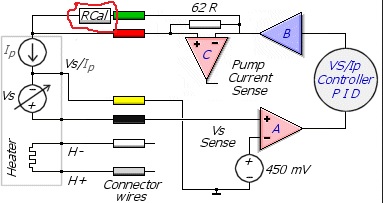
The oxygen sampling element in a wideband sensor samples from an internal chamber. The wideband sensor is able to adjust the oxygen content of the internal chamber through a Pump cell. The PCM will send a current through the pump cell in one direction to cause oxygen ions to enter the internal chamber from atmospheric air. Thus increasing the oxygen content across the sampling element. To decrease the oxygen content, the PCM just reverses the current direction. The PCM monitors how much current and which direction is required to make that exhaust sample in the internal chamber be stoich.
So a narrowband sensor reads the oxygen in the exhaust and tells the PCM if it's above or below stoich. A wideband tells the PCM how much oxygen is needed to make an exhaust sample be stoich...
A narrowband sensor is not able to actually find stoich. Therefore its signal is always switching back and forth. A wideband sensor is able to tell the PCM how to reach stoich. Therefore its signal is relatively stable and flat.
So really wideband sensors aren't very complex. What's complex about them is trying to find information on how individual systems interpret their data and how they represent it to you! How every manufacturer represents them differently and gives you access to them differently!
Please Log in or Create an account to join the conversation.
- Tyler
-
Topic Author
- Offline
- Moderator
-
- Full time HACK since 2012
- Posts: 6129
- Thank you received: 1544
ecwurban wrote: So really wideband sensors aren't very complex. What's complex about them is trying to find information on how individual systems interpret their data and how they represent it to you! How every manufacturer represents them differently and gives you access to them differently!
Truth.
As usual, the best way I've found to get familiar is to hook up to known good cars and take them for a drive.
Please Log in or Create an account to join the conversation.
- chief eaglebear
-
- Offline
- Platinum Member
-
- Posts: 340
- Thank you received: 70
Please Log in or Create an account to join the conversation.
- Tyler
-
Topic Author
- Offline
- Moderator
-
- Full time HACK since 2012
- Posts: 6129
- Thank you received: 1544
Please Log in or Create an account to join the conversation.