O2 Sensor Diagnostics
- Rukerin
-
 Topic Author
- Offline
- Junior Member
-

- Posts: 26
- Thank you received: 2
Please Log in or Create an account to join the conversation.
- Tyler
-

- Offline
- Moderator
-

- Full time HACK since 2012
- Posts: 6129
- Thank you received: 1544
Paul did do a two-part series on such sensors, worth watching:
Unfortunately, the Toyota that was featured in the video converts the sensor current into a voltage reading for scan data, instead of displaying the actual sensor current. Kinda goofy.
Wikipedia wrote: The wide-band O2 sensor looks similar in appearance to the regular zirconia O2 sensor. Its inner construction and operation are totally different, however. The wide-band O2 sensor is composed of two inner layers called the reference cell and the pump cell. The ECM’s AFR sensor circuitry always tries to keep a perfect air/fuel ratio inside a special monitoring chamber (diffusion chamber or pump-cell circuit) by way of controlling its current. The AFR sensor uses dedicated electronic circuitry to set a pumping current in the sensor’s pump cell. In other words, if the air/fuel mixture is lean, the pump cell circuit voltage momentarily goes low and the ECM immediately regulates the current going through it in order to maintain a set voltage value or stoichiometric ratio inside the diffusion chamber.
As for testing them, it somewhat depends of on the YMM of the vehicle, and the sensor installed. Some, like Honda and Toyota four-wire sensors, are dead simple to test. Others are more complex. If you have a specific vehicle in mind, or one you want to experiment with, let us know!
Please Log in or Create an account to join the conversation.
- lxuser
-
- Offline
- New Member
-

- Posts: 4
- Thank you received: 2
Try to read this first:
wbo2.com/lsu/lsuworks.htm
and then look here:
tekniwiki.ngk.de/desktop/
You pick the lambda sensors in the drop down menu and pick the broadband ones.
I have quite good looking troubleshooting guide (not tested yet) with scope wave forms but it is not in English (I will try to translate and put it here later) and if you do not have this basic knowledge at least what it is pump cell and measuring cell it will not help much.
Tomas
Please Log in or Create an account to join the conversation.
- lxuser
-
- Offline
- New Member
-
- Posts: 4
- Thank you received: 2
Broadband lambda (O2) sensor
Failure of broadband lambda (O2) sensor (BBS) is possible to detect only two or more channel oscilloscope. Test comes from fact that the same as the Zirconium lambda (O2) sensor is the BBS capable of producing voltage according the oxygen content in the exhaust manifold.
If we are switching oxygen content in exhaust (acceleration- without oxygen, deceleration- oxygen), must both oxygen cells of BBS in disconnected state from ECU/PCM show correct function.
Symptoms of bad BBS (depends on intelligence of system)
- Check engine light is on
- Light jerking during acceleration caused by incorrect A/F ratio change
Frequent error reports
- Mixture too rich/lean
- Lambda (O2) sensor, incorrect (absurd) signal, short to ground, to battery voltage, no activity, and so on.
Live data
- Value of lambda (% or V) is out of tolerance
- Adaptation values of mixture are out of tolerance
- Spray duration (injection period) out of tolerance (spec)
Conditions for measurement
- Calibration resistor in terminal (connector) of lambda (O2) sensor is not open (ohm check)- should be 62 ohms
- Warmed up engine
- Without more serious problems (misfire, no start, barely running and so on.)
- Lambda (O2) sensor warmed up to working temperature (working heater element)
Test procedure
- All measurements should be made from connector side of BBS (5 pin), not on side of wiring harness (6 pin).
- Measuring against negative terminal of car battery, find raised ground of BBS (lowest measured voltage- typical 2,5V; 3,7V; 4V), possible with multimeter
- Connect ground lead from oscilloscope to the raised ground of BBS
- Connect two channels of oscilloscope one to voltage of pump cell and other to the measuring cell; (by ruling out the pins for heater)
- Start warmed up engine and make several ( 3 to 8 ) accelerations to max rpm with deccelerations lasting aprox. 4 seconds (warming up the lambda (O2) sensor).
- During last deceleration disconnect the connector of BBS and make again several equal accelerations (actual test of lambda sensor)
Evaluation of actual test in disconnected state
- During acceleration must signal of pump cell as first change its voltage approx. 800mV to negative value. If not- change BBS
- Signal of measuring cell can’t stay in negative values (-100 mV and more) and it’s voltage must significantly drop not until reaching maximum negative value on pump cell. If not- change BBS
- Maximum voltage of measuring cell must reach minimum of 0,7 V. If not- change BBS
Before replacing the BBS it is necessary to check for possible cause of it’s failure (extreme deviation from demanded A/F ratio, cylinder misfire- unburned fuel, burning of oil or coolant, or other chemical poisons- silicone and so on.)
Oscilloscope setup
- Trigger: internal
- t : pic.1 - 2s/div, pic.2 - 50ms/div
- frequency : approx. from 100Hz
- Ch.1 (blue) : 0,1 V/div – raised ground of both BBS cells ( not necessary to connect)
- Ch.3 (red) : 0,1V/div -- signal from pump cell
- Ch.4 (yellow) : 0,1V/div – signal from measuring cell
- GND: raised ground of both BBS cells (connected with ch.1 ), from reason of measuring voltage in it’s disconnected state (for disconnected BBS have negative terminal of car battery no bond- feedback, relation)
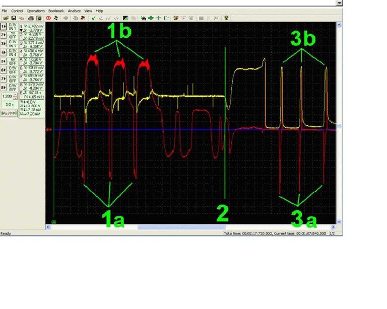
Description of oscillogram (picture from oscilloscope)
Connected connector
1a- 3x acceleration.
In phase of mixture enrichment (oxygen-free state in exhaust) is voltage from pump cell (red) -0,7 V and in the opposite the voltage of measuring cell (yellow) slightly raised.
1b- 3x deceleration.
In phase of disconnected injection (oxygen state in exhaust) is voltage of pump cell (red) at it’s maximum (-0,8 V) and in the opposite voltage of measuring cell (yellow) slightly lowed.
WARNING! Reached voltages of both cells are result of work of both cells + control unit and might according the stage of enrichment, process of acceleration and other factors change- do not evaluate these values. Because of this must follow the test with disconnected connector. Only this way we found out the working of BBS itself.
2- moment of disconnection of BBS
3a- 3x acceleration.
Pump cell acts similar even in disconnected state
3b- 3x deceleration.
Measuring cell reacts similar as cell of jump (narrow band) lambda (O2) sensor during acceleration.
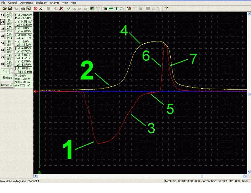
Detail of behavior of voltage on both cells in disconnected state
1 – acceleration
Only voltage of pump cell reaches max. negative value 0,8V (chemical boundaries of Zirconia cell), because measuring cell didn’t noticed the change of oxygen (measuring cell is separated by difuse slit- gap)
2
Only after return of voltage of pump cell to zero voltage is starting to appear on measuring cell voltage (through difuse slit- gap is starting to show oxygen change)
3
Voltage on pump cell is starting to gradually decrease (penetration of oxygen change through difuse slit- gap is causing balancing of oxygen environment on both electrodes of pump cell)
4
If acceleration causes sufficiently fast mixture enrichment, voltage on measuring cell must reach maximum of 0,8V.
5
If the enrichment phase is long enough, voltage on pump cell is staying on 0 value (without oxygen changes)
6 – deceleration
Only voltage of pump cell notices significant change on oxygen state (shut down of fuel injection). Difuse slit- gap is preventing of the quick change on measuring cell.
7
Oxygen state came through difuse slit- gap to measuring cell, in pump cell the oxygen states on both it’s electrodes are being balanced
Note: translated excerpt and pictures from:
Zvyšování kvality výuky
technických oborů
Klíčová aktivita V.2
Inovace a zkvalitnění výuky
směřující k rozvoji
odborných kompetencí
žáků středních škol
Téma V.2.12
Měření parametrů
Kapitola 28
Širokopásmová lambda sonda
Libor Blahuta
30.9.2012
Please Log in or Create an account to join the conversation.
- Noah
-

- Offline
- Moderator
-
- Posts: 5050
- Thank you received: 1125
Please Log in or Create an account to join the conversation.
- lxuser
-
- Offline
- New Member
-
- Posts: 4
- Thank you received: 2
Tomas
Test of the broadband lambda (O2) sensor, faults
Commonly it is anticipated that broadband lambda (O2) sensor is perfectly guarded by it’s own diagnostics. However its own diagnostics is not capable of detecting all the faults of broadband lambda sensor. Sometimes are stored in memory error messages such as mixture adaptation out of tolerance, sometimes there is no error in memory, but there are present symptoms of not properly working system, such as for example negative affected ride comfort, raised fuel consumption, not passed emission test, problems with engine idle or in partial or full engine load, reduced power and so on.
Our innovative diagnostic method discovers every problem occurring in regulation of broadband lambda (O2) sensor nearly with confidence.
Faults detected by test of broadband lambda (O2) sensor in disconnected state.
Yellow- signal in measuring cell
Red- signal of pump cell
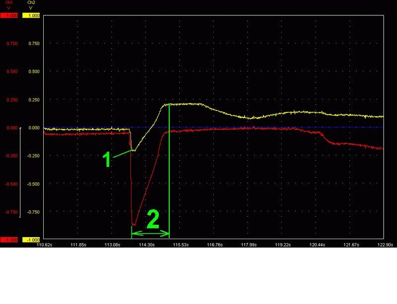
1. Fault (defect)- detail of voltage progress of both cells in disconnected state (50ms/div)
Engine- VW 1,8T AUQ (engine code)
Error messages- none
Symptoms of fault (defect)- reduced power
1- Acceleration
Dashed lines show correct of voltage progress on both cells.
2- Stoppage of current move of oxygen change from pump cell (its voltage has dropped) to measuring cell, which nearly didn’t even recognized the change.
Therefore the diffusive slit- gap is impassable.
3- Deceleration
Evaluation- signal of BBS is different from representative (characteristic) pattern- faulty BBS.
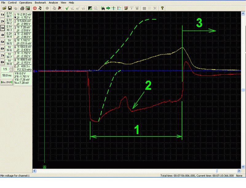
2. Fault- detail of voltage progress of both cells in disconnected state (1,22s/div)
Engine- VW 1,6 BFQ (engine code)
Error messages- 16555 : system of fuel metering – mixture too lean (sporadic fault)
Symptoms of fault (defect)- hesitation on acceleration
1- Measuring cell shows negative voltage during acceleration
2- acceleration
Evaluation- signal of BBS is in negative values – faulty (defective) BBS
Broadband lambda (O2) sensor (Bosch with red wire)
Construction of this lambda sensor is more complicated than the narrow band. This one has not only Nernst cell, but needs so called pump cell.
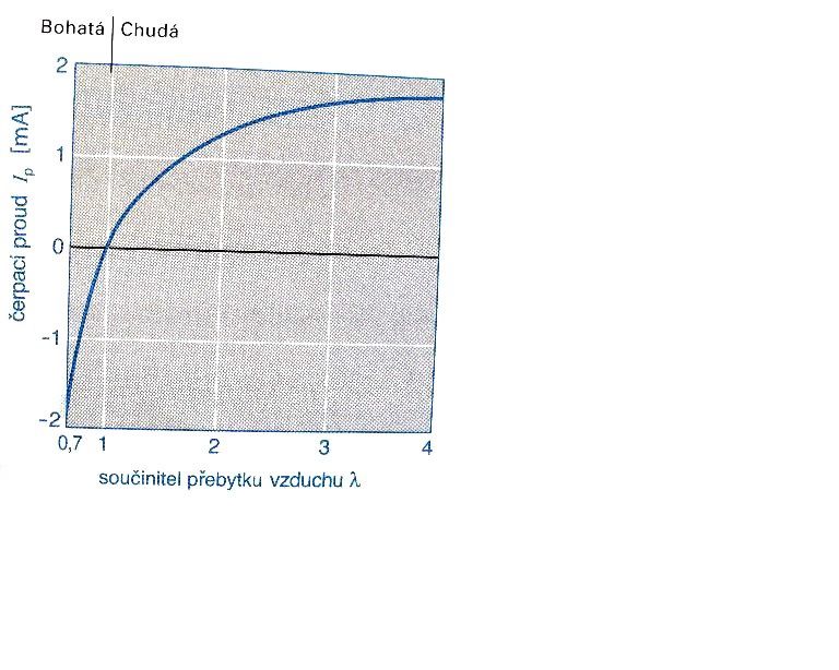
Čerpací proud Ip – pump current
Součinitel přebytku vzduchu λ – air-fuel ratio λ
Measuring with oscilloscope
- for measuring broadband (O2) lambda sensor is necessary two channel oscilloscope, measuring leads can’t be connected inside of oscilloscope with ground -> in the point of connection of oscilloscope in connector of lambda (O2) sensor is not zero potential (0V), but voltage 2,5-4,5V depending on design. <-> necessary to use oscilloscope with floating ground (for example PICO 4425).
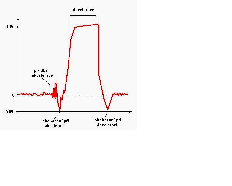
Decelerace- deceleration
Prudká akcelerace- rapid acceleration
Obohacení při akceleraci- enrichment during acceleration
Obohacení při deceleraci- enrichment during deceleration
Connection of oscilloscope HD 34 (DIANA)
- connect the power cables of oscilloscope to the car battery
- connect CH1 (first channel of oscilloscope) to PIN 2 (so called 6-wire, goes to connector on side of wiring harness, pin 2 goes to resistor inside the connector).
- Connect CH2 (second channel of oscilloscope) to PIN 6 (red wire of lambda (O2) sensor so called pumping).
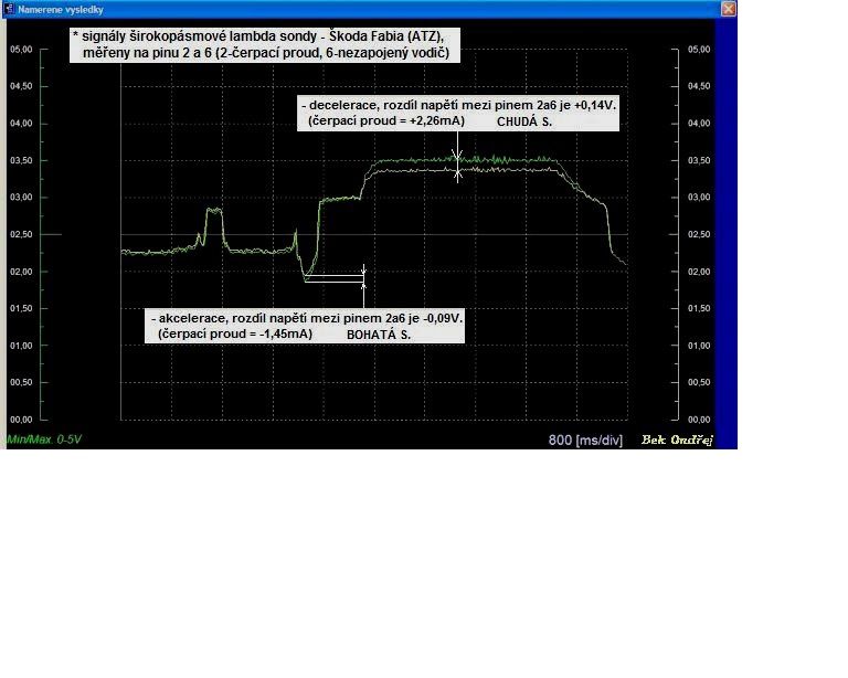
Signály širokopásmové lambda sondy – Škoda Fabia (ATZ), měřeny na pinu 2 a 6 (2- čerpací proud, 6- nezapojený vodič)- signals of broadband lambda (O2) sensor – Škoda Fabia (ATZ), measured at pin 2 and 6 (2- pump current, 6- unconnected wire in wiring harness)
Decelerace, rozdíl napětí mezi pinem 2 a 6 je + 0,14V. (čerpací proud = + 2,26mA) CHUDÁ S. – deceleration, difference of voltages between pin 2 and 6 is 0.14V. (pump current = + 2,26mA) LEAN mixture.
Akcelerace, rozdíl napětí mezi pinem 2 a 6 je -0,09V. (čerpací proud = - 1,45mA) BOHATÁ S. – acceleration, difference in voltages between pin 2 and 6 is – 0,09V (pump current = -1,45mA) RICH mixture
- Measuring is done during rapid acceleration – full open throttle with subsequent release of gas pedal – deceleration
Calculation of pump current
From measured graph we subtract differences between CH1 and CH2 -> X. Substituting to formula Ip=X/R (Resistor is given by ECU/PCM 61.9 ohms) we calculate the pump current.
We have 3 states where the measuring is done: idle, rapid acceleration and subsequent deceleration.
1) Idle- voltage on pin 2 and 6 is the same - > curves are on top of each other.
Ip = 0 mA difference in voltages X -> X = 0
Pump current Ip -> Ip = 0
2) Acceleration – voltage on pin 2 is lower as on pin 6
Ip = -0.8 to -1.6 mA difference in voltages X has negative value -> X = -50 to -150mV
Pump current Ip has negative value as well -> Ip = - 0.8 to -1.6mA
Rich mixture- negative values
3) Deceleration- voltage on pin 2 is higher than on pin 6
Ip = 2.4 to 4 mA difference of voltage X has positive value -> X= 150 to 250 mV
Pump current Ip has positive value too -> Ip = 2.4 to 4 mV
Lean mixture – positive values
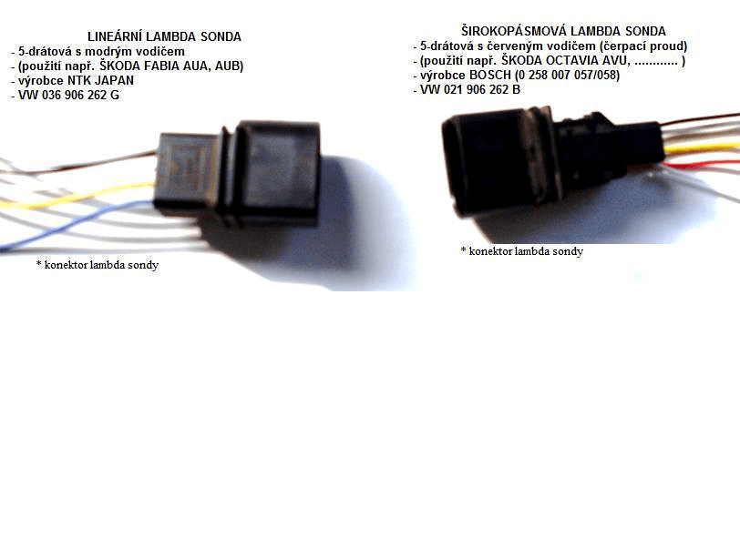
Lineární lambda sonda- Linear Lambda sensor
- 5 wire with blue wire
- Used on for example Škoda Fabia AUA, AUB
- Manufacturer NTK Japan
- VW 036 906 260 G
Širokopásmová lambda sonda- Broadband Lambda sensor
- 5 wire with red wire (Pump current)
- used on for example Škoda Octavia AVU, ...
- manufacturer Bosch (0 258 007 057/058)
- VW 021 906 262 B
*konektor lambda sondy- lambda (O2) sensor connector
Note: translated excerpt and pictures from:
Zvyšování kvality výuky
technických oborů
Klíčová aktivita V.2
Inovace a zkvalitnění výuky
směřující k rozvoji
odborných kompetencí
žáků středních škol
Téma V.2.12
Měření parametrů
Kapitola 28
Širokopásmová lambda sonda
Libor Blahuta
30.9.2012
Please Log in or Create an account to join the conversation.