Secondary ignition waveform
- Andy.MacFadyen
-

- Offline
- Moderator
-

- Posts: 3357
- Thank you received: 1037
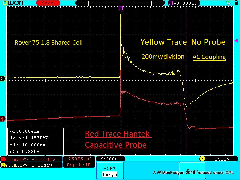
Yellow Trace Channel 2 --- No Probe No Physical Connection ! 200mv/div :dry:
" We're trying to plug a hole in the universe, what are you doing ?. "
(Walter Bishop Fringe TV show)
Please Log in or Create an account to join the conversation.
- Andy.MacFadyen
-
- Offline
- Moderator
-
- Posts: 3357
- Thank you received: 1037
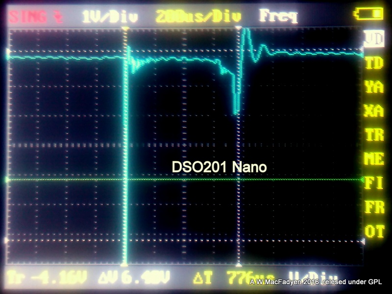
I have since tried it with DSO201 Nano and it also works nicely with that.
" We're trying to plug a hole in the universe, what are you doing ?. "
(Walter Bishop Fringe TV show)
Please Log in or Create an account to join the conversation.
- VizoEdward
-

- Offline
- New Member
-

- Posts: 13
- Thank you received: 1
In my case, I have utilize the Hantek HT25COP and Pico pp357(TA204). Neither of the two utilize a clamp around the HT wire, the probe is rested on top of the coil. These are the ones in question? Are this probes made to be used with out external attenuation devices placed in line with the sensing circuit.?. Or are they plug and go devices like the should be. In any case I have received notes from Pico and Snap On support Teams on the matter. Pico mention that their tool does not need nothing on their hardware/software units. Snap on goes about telling about the same. Most important I wanted to know why? my trace changes color, as I have previously mention on several post today. To Snap On it seem I have a problem with the screen set up.
Is the solution to this matter to try again with a different voltage scale? so it seem to Snap On. Simple. But the point is that I would like to have a little of more info before I risk the health of my dear scope. Which by the way is a Vantage Pro one that I got through a lot of effort and to damage it for ignorance will indeed be not a good thing. The biggest attenuator that I own is a 20:1, all with be easy if I had one 1,000 to 1 or even one(10K) like it is used on the capacitive clamp type. In that scenario will plug it, check result and most certainly that way answer every thing for me but I do not have it.
So again, if any light on the matter can be pointed this way. Thanks a lot
Please Log in or Create an account to join the conversation.
- Andy.MacFadyen
-
- Offline
- Moderator
-
- Posts: 3357
- Thank you received: 1037
At Scope BNC: + to Ground 33k ohms,
At Pickup: + to Ground 33K ohms
Scope end to Pickup End 0 Ohms on both + and Ground conductors.
So any over voltage protection and attenuation going on inside the black box on the lead isn't being done by reisstors
" We're trying to plug a hole in the universe, what are you doing ?. "
(Walter Bishop Fringe TV show)
Please Log in or Create an account to join the conversation.
- VizoEdward
-
- Offline
- New Member
-
- Posts: 13
- Thank you received: 1
Let me ask you: I do not know the brand of scope you use, looking at the photos you send with the capture waveform it seem to be a Hantek. Now, does it change color on the trace on you when selected voltage scale is under the value of the actual captured signal. For example, in my case I selected a scale of 15KV per screen to view the secondary @ idle, but I can see the trace passing that point way up out of the screen. Is it possible that is the reason I am having this issue of change of color on my trace? Is this normal on any brand of scope or is it unique to Snap on products?. O worst yet indeed more voltage is coming in to the scope that it can handle?
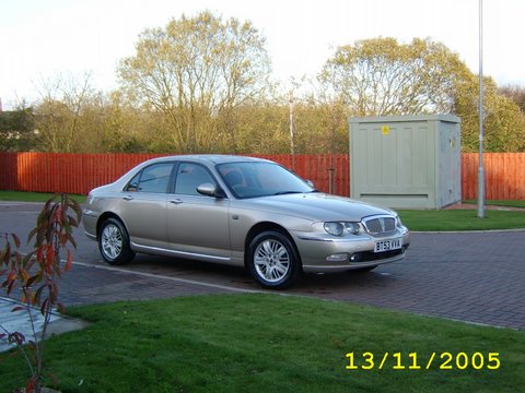
By the way good trick on the capture o f the rover trace with your hand over the coil ! . Is it a 75 Land Rover?. It does recall some fun memories.
Please Log in or Create an account to join the conversation.
- Andy.MacFadyen
-
- Offline
- Moderator
-
- Posts: 3357
- Thank you received: 1037
My main scope is an Owon SDA7120v with the optional battery I like it because I like having real knobs and buttons It isn't perfect for automotive work but I find it quick and easy to use and I got it at a very good price. I have a Hanktek 1008 I keep is reserve in case I need more than two channels.
---

I was sitting waiting for the grand kids coming out of school and did some web browsing on protecting scope inputs and capacitive probes, interesting.
From what I can gather the output voltage of a capacitive probe is controlled by simply linking the ground and signal wires by a ressistor and capictor in parrallel.
The over voltage protection in the scope is also pretty simple just 4 diodes that act the same way as the zenner diode in a motorcycle voltage regulator and simply dump any excess voltage back to ground.
That captures were taken not from a Land-Rover but this car a now high mileage Rover 75 the last car model Rover made before they went bust 11 years later we still have a couple of them in the family fleet --- we used have a lot of various Rovers and MGs but the family are going Nissan and Renault
" We're trying to plug a hole in the universe, what are you doing ?. "
(Walter Bishop Fringe TV show)
Please Log in or Create an account to join the conversation.
- VizoEdward
-
- Offline
- New Member
-
- Posts: 13
- Thank you received: 1
My Snap On Vantage Pro bundle is 11.4 ( circa 2010) not even close to what Mr. Danner operate. Got it used, but still a treasure worth keeping it safe from misusage...........hope.
On any case, looks like my main concern with the usage of the HP25COP/Pico pp357) on this scope still inconclusive. Should I give it a green light to try the same capture on a different voltage scale?. Apparently that what Snap On thinks. I am tempted to do it but...............certainly will be nice to have the right answer?
Did you check the Hantek item HT25COP? Aside for what is happening to me it seem it is a better tool than the HT25.
Please Log in or Create an account to join the conversation.
- rob.dotterer
-
- Offline
- New Member
-
- Posts: 1
- Thank you received: 0
Please Log in or Create an account to join the conversation.
- VizoEdward
-
- Offline
- New Member
-
- Posts: 13
- Thank you received: 1
Now, Rob: First, a question: Are you using the Hantek HT25 (capacitive) wire with a clamp on one end, BNC connector at the other. Or are you using the Hantek HT25 COP ignition probe with the handle on one end, paddle( that you rest on the coil) at the other?. With both I am getting a trace I can certainly work. But the selection of the scope mode, scaling, trigger,etc must be change according to which of the two is used.
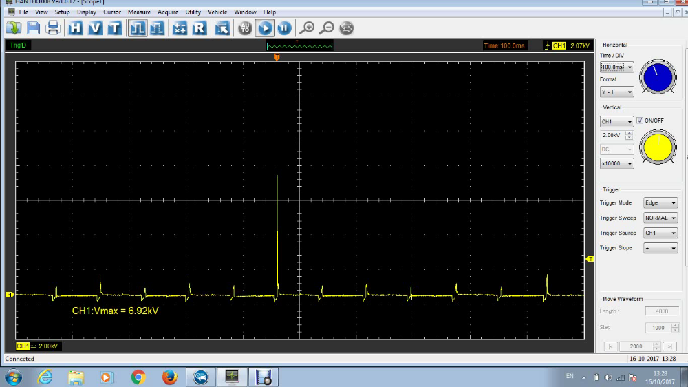
Example: A Secondary ignition waveform, COP system, at idle*.
With the HT25: Lab scope: Volts DC 400mv/div (2Vper screen); 10ms time; Channel 1 normal trigger@ rising slope with a 2ms delay, level 1.0V. Use the HT extension lead, Keep it away from other coils .
With the HT25COP: Ignition scope,single cylinder Ignition: Volts KV at 15KV; 20ms; channel 1, normal trigger @rising slope, 10ms delay, level 4KV. Important: Install a 20:1 attenuator! , rest the probe paddle square on top of the selected coil.
*To test at higher RPM adjust accordingly.
Please Log in or Create an account to join the conversation.
- Noah
-

- Offline
- Moderator
-
- Posts: 5051
- Thank you received: 1125
That's absolutely wild! I'm admittedly novice when it comes to secondary waveforms, but I have never seen or heard of anyone capturing a waveform with that method.Andy.MacFadyen wrote: The method used to do the capture was to use a basic crocodile clip lead. Scope ground connected to a block ground, scope positive is gripped in one hand while the palm of the other hand is simply held about 2 to 6 inches above the coil.
I have since tried it with DSO201 Nano and it also works nicely with that.
Please Log in or Create an account to join the conversation.
- Andy.MacFadyen
-
- Offline
- Moderator
-
- Posts: 3357
- Thank you received: 1037
Interestingly the alternator ripple is alao being picked up--- that is really crazy.
I have seen a short video on YouTube of another method that I will try out next time I get a suitable vehicle in.
link to video
" We're trying to plug a hole in the universe, what are you doing ?. "
(Walter Bishop Fringe TV show)
Please Log in or Create an account to join the conversation.
- SailorBob
-

- Offline
- Elite Member
-

I took a short one minute video and captured a few individual wave forms. Going over that video in slow motion I saw quite a variety of waveform shapes, however the fire lines were all about 2 milliseconds which is supposedly pretty good and close to the maximum possible. I don't think the scope was displaying every single spark event because I had the trigger set fairly high, however these two basic waveforms were the most common:
This seems pretty normal, but I was wondering why that second spike was so high? Just allot of energy to wring out?
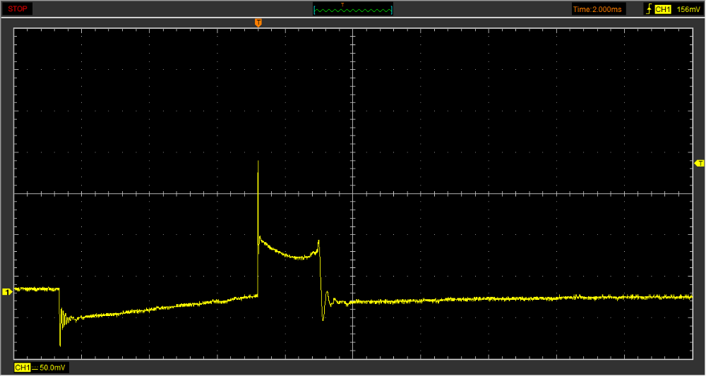
This is the other common one, and I'm assuming this is the waste spark?
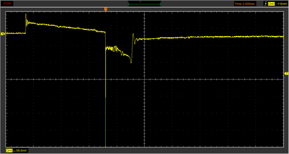
My odd numbered cylinders where upside down like this. I wanted to do the 10k X scaling for this probe, but couldn't get it to work, so I just left it in mV.
I mentioned that I saw a variety of waveforms on slow-mo in the linked video; how much do I care about the exact shape especially of regarding the shape of the burn line?
Please Log in or Create an account to join the conversation.
- Andy.MacFadyen
-
- Offline
- Moderator
-
- Posts: 3357
- Thank you received: 1037
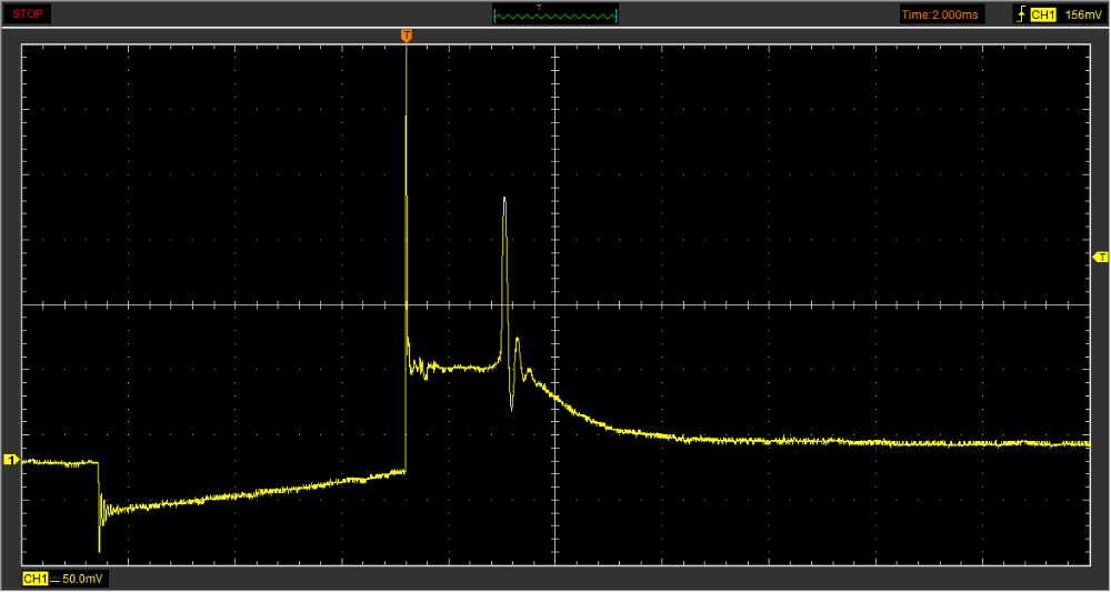
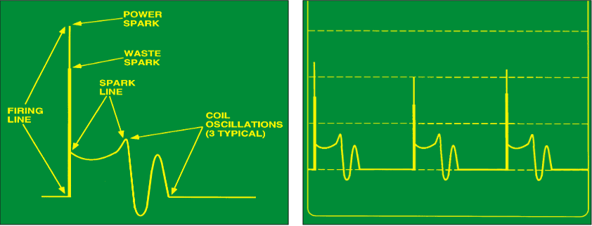
When looking at ignition secondary traces on wasted spark systems the trigger level should be set high enough to trigger only ignition firing sparks not wasted sparks.
If you find a significant "toe" voltage at the end of an actually firing spark then it could point to a plug lead or plug shorted to ground or a spark plug gap set too narrow.
With a wasted spark system the companion cylinder can also affect the spark line on the cylinder you are looking at.
" We're trying to plug a hole in the universe, what are you doing ?. "
(Walter Bishop Fringe TV show)
Please Log in or Create an account to join the conversation.
- SailorBob
-
- Offline
- Elite Member
-
Please Log in or Create an account to join the conversation.
- SailorBob
-
- Offline
- Elite Member
-
I also saw some things I quite frankly didn't understand. When I set it to 20ms/2kv with a 5kv trigger I saw these shapes on both sides of the spark:
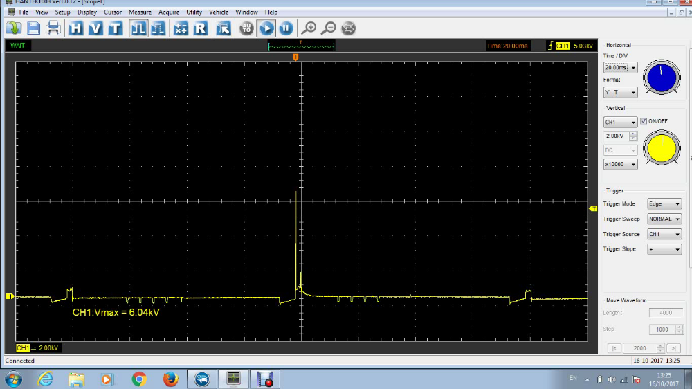
Then when I set it to 100ms/2kv with a 2kv trigger things got stranger:
What am I seeing? Is there something wrong with my scope or setup? I was using an HT25 inductive clamp probe attached to the plug wire and grounded to the engine.
Maybe I was picking up noise from other things because I grounded the probe to the engine ground and not the battery?
The engine was running about 750rpm here which translates to 6.25 hertz, which would give me a spark on that plug once every 1.5 seconds approximately.
Please Log in or Create an account to join the conversation.
- Andy.MacFadyen
-
- Offline
- Moderator
-
- Posts: 3357
- Thank you received: 1037
On a waste spark system with the Hantek you will only really to be one spark in useful detail.
The article and illustrations in Motor magazine are showing what you would see on a old style cathode ray oscilloscope, with a cathode ray tube the glow of the phosphor coating has persistence ie it continues to glow after the trace has moved on, you won't see the two traces superimposed on Hantek.
Also on modern ignition system because coils are smaller and spark plug gaps are wider there is less energy trapped in the coil when the spark dies out so the coil oscillations tend to be smaller so don't expect to see large oscillations as in the graphics.
The real guru of ignition scope work is a guy called Jim Morton he has some video on YouTube --- serious stuff worth watching
" We're trying to plug a hole in the universe, what are you doing ?. "
(Walter Bishop Fringe TV show)
Please Log in or Create an account to join the conversation.
- SailorBob
-
- Offline
- Elite Member
-
Please Log in or Create an account to join the conversation.
- juergen.scholl
-

- Offline
- Platinum Member
-

- Active partschanger
- Posts: 1233
- Thank you received: 462
sure that Jim Morton is a true master not only of ignition scoping but on automotive diagnostics in many regards; as well as Bill Fulton is. From the latter is the famous "10 minutes secondary quick check" approach, which can be found within the TST videos too, or AVI.
The true ignition guru to me is the former ALLEN engineer Mac Vandenbrink. His alltime favorite is called "exploring combustion behaviour through the eyes of a scope" and this is just about what the title indicates.
You still may find this thru AES wave in DVD form and you may really enjoy to "discover the hidden secrets of scope pattern interpretation, if you do not know it already.
An expert is someone who knows each time more on each time less, until he finally knows absolutely everything about absolutely nothing.
Please Log in or Create an account to join the conversation.
- Dylan
-
- Offline
- Moderator
-
- Belgium, Europe
- Posts: 1462
- Thank you received: 327
Here's a video from TST seminars with Mac Vandenbrink:
Please Log in or Create an account to join the conversation.
- SailorBob
-
- Offline
- Elite Member
-
Please Log in or Create an account to join the conversation.